Method for measuring current-voltage characteristic

a current-voltage characteristic and characteristic technology, applied in the field of current-voltage characteristic measurement methods, can solve the problems of difficult measurement, deviating from the actual current-voltage characteristic, unrealistic measurement, etc., and achieve the effect of low heat production and high accuracy

Active Publication Date: 2018-07-05
ROHM CO LTD
View PDF0 Cites 7 Cited by
  • Summary
  • Abstract
  • Description
  • Claims
  • Application Information

AI Technical Summary

Benefits of technology

[0012]To cope with the above-mentioned problem encountered by the present inventors, the present invention aims to provide a method for measuring a current-voltage characteristic with low heat production and high accuracy.

Problems solved by technology

Thus, a large amount of heat is produced under a high-current / high-voltage condition, and it is thus unrealistic to measure, with a curve tracer, a current-voltage characteristic of a power transistor used under such a condition.
The load curve of the power transistor represented by the dash-dot line in FIG. 7 has a maximum power point X where a high current and a high voltage are simultaneously applied, and it is difficult to measure this region by use of the curve tracer due to the power limit of the device and the heat produced by and destruction of the power transistor.
Thus, when the current-voltage characteristic of the SiC-MOSFET is acquired, if, as with the current-voltage characteristic of the Si-MOSFET, the drain current in the saturation region is assumed to remain constant, the acquired result greatly deviates from the actual current-voltage characteristic; this greatly affects the accuracy of the device model.
However, according to the conventional method proposed in Non-Patent Document 1, the start and end points of the rise time of the drain current are not clearly defined; this tends to cause variations in the measurement result.

Method used


Image

  • Method for measuring current-voltage characteristic
  • Method for measuring current-voltage characteristic
  • Method for measuring current-voltage characteristic

Examples


Embodiment Construction

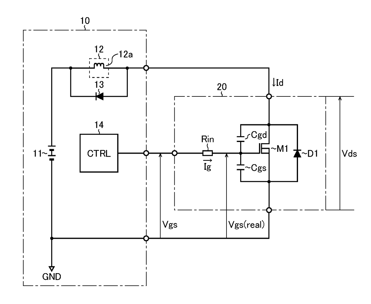
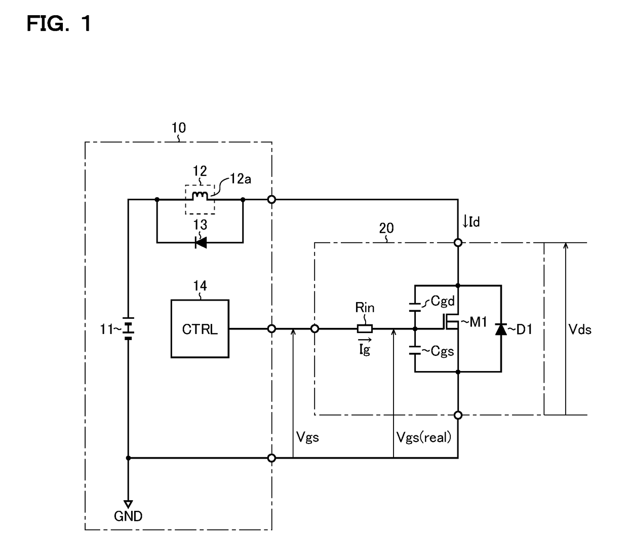
[0022]Measurement Device: FIG. 1 is an equivalent circuit diagram showing a measurement device according to one embodiment that is used when a current-voltage characteristic of a switching device is measured. The measurement device 10 according to the embodiment includes a voltage source 11, a current source 12, a diode 13, and a controller 14, and measures the current-voltage characteristic of the switching device 20 (here, the Id−Vds characteristic, that is, the relationship between the drain current Id and the drain-source voltage Vds of the switching device 20).

[0023]The switching device 20 is a semiconductor switching device which is a measurement target of the measurement device 10, and in FIG. 1, an N-channel MOS (metal-oxide-semiconductor) field-effect transistor M1 is used as the switching device 20. In particular, examples of the transistor M1 whose current-voltage characteristic is considered to be preferably measured by use of the measurement device 10 proposed herein in...


PUM


Abstract

A method for measuring a current-voltage characteristic (Id−Vds characteristic) representing the relationship between the drain current Id (or collector current) and the drain-source voltage Vds (or collector-emitter voltage) of a transistor M1 includes setting the drain current Id (or collector current) and the drain-source voltage Vds (or collector-emitter voltage), measuring the gate-source voltage Vgs (or gate-emitter voltage) and the gate current Ig of the transistor M1 in a switching transient state, and acquiring the current-voltage characteristic (Id−Vds characteristic) of the transistor M1 based on the measurement results of the gate-source voltage Vgs (or gate-emitter voltage) and the gate current Ig.

Description

[0001]This application is a continuation of U.S. patent application Ser. No. 15 / 473,114 filed Mar. 29, 2017, which is based on Japanese Patent Application No. 2016-065893 filed on Mar. 29, 2016, the contents of both of which are hereby incorporated by reference in their entirety.BACKGROUND OF THE INVENTION1. Field of the Invention[0002]The present invention relates to a method for measuring a current-voltage characteristic.2. Description of Related Art[0003]To create a device model of a transistor used in computer simulations such as SPICE (simulation program with integrated circuit emphasis), it is essential to measure the current-voltage characteristic of the transistor (for example, the Id−Vds characteristic, that is, the relationship between the drain current Id and the drain-source voltage Vds of a MOSFET). The current-voltage characteristic is often measured by use of a curve tracer.[0004]With a curve tracer, for example, while a predetermined gate-source voltage is applied to...

Claims


Application Information

Patent Timeline
Patent Type & Authority Applications(United States)
IPC IPC(8): G01R31/26G06F17/50
CPCG06F17/5036G01R31/2601G01R31/2621G01R31/2603G06F30/367
Inventor YANAGI, TATSUYAOTAKE, HIROTAKASAKAIRI, HIROYUKIKURODA, NAOTAKA
Owner ROHM CO LTD
Why Eureka
Try Eureka