

Laser welding method, high pressure fuel supply pump, and fuel injection valve
a high-pressure fuel supply and welding method technology, applied in metal working equipment, manufacturing tools, transportation and packaging, etc., can solve the problems of large change in effective welding length, disadvantageous need for excessive input heat, and inability to apply laser beam vertically to the weld portion, so as to improve the aiming position tolerance, increase the effective welding length, and increase the welding width
- Summary
- Abstract
- Description
- Claims
- Application Information
AI Technical Summary
Benefits of technology
Problems solved by technology
Method used
Image

Examples
embodiment 1
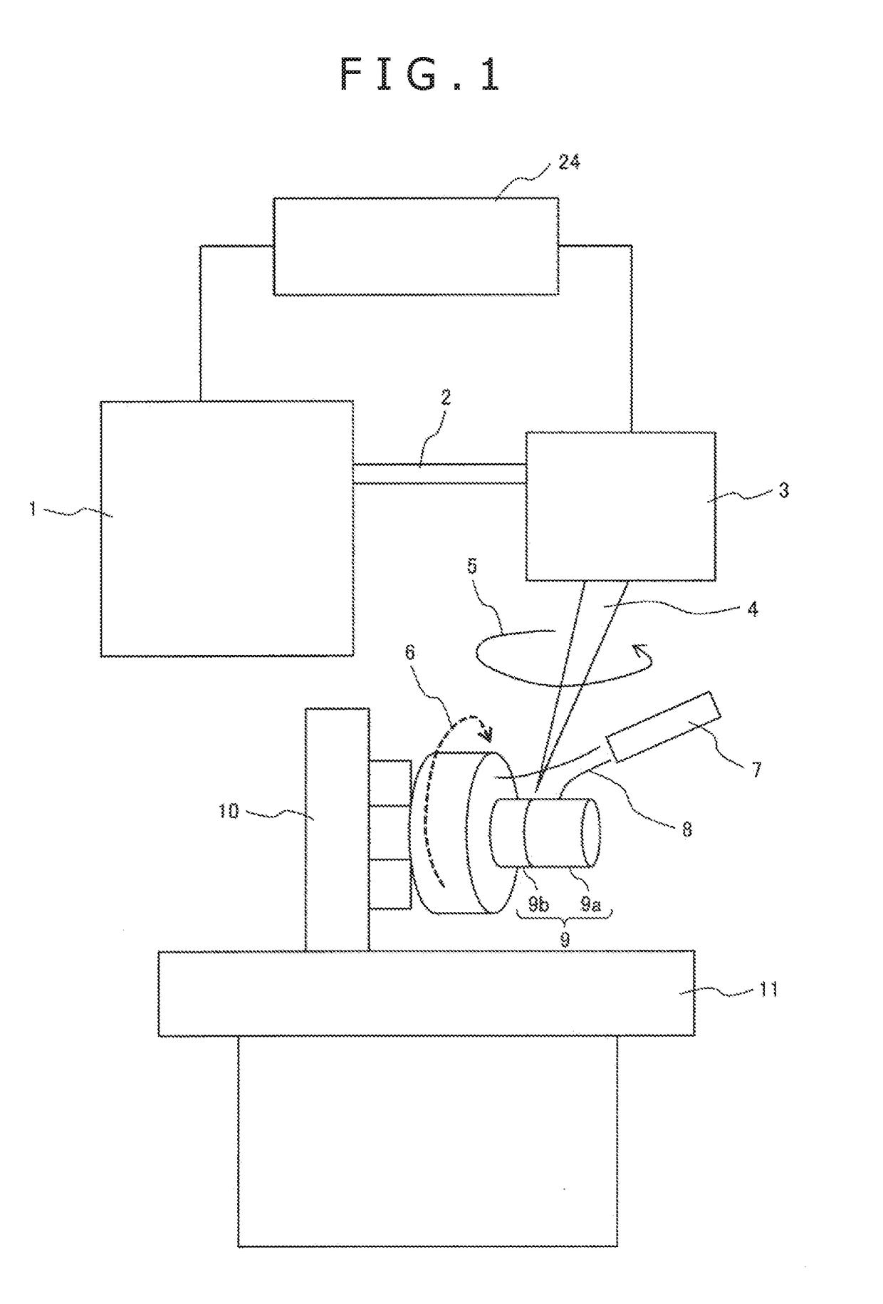
[0037]FIG. 1 is a schematic diagram illustrating a laser welding apparatus according to embodiment 1.
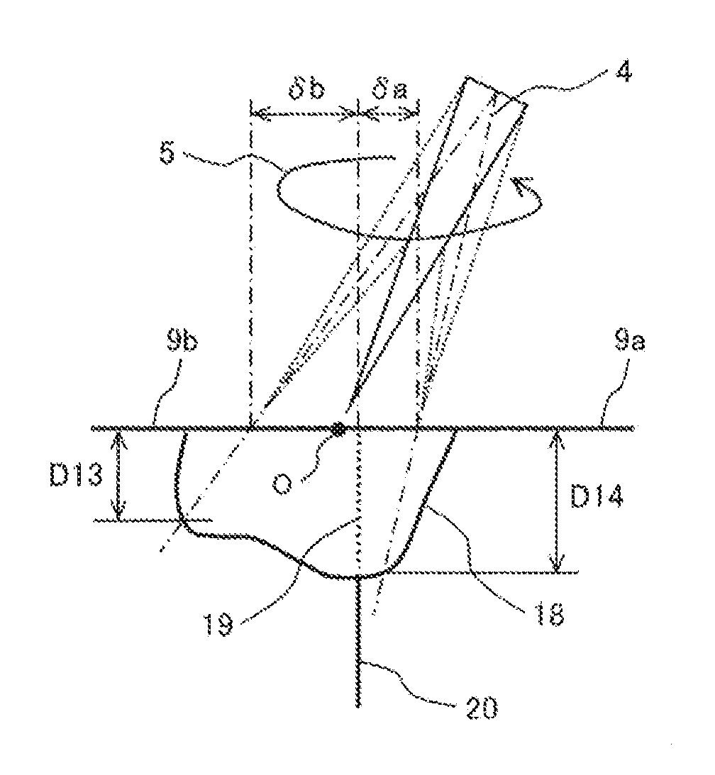
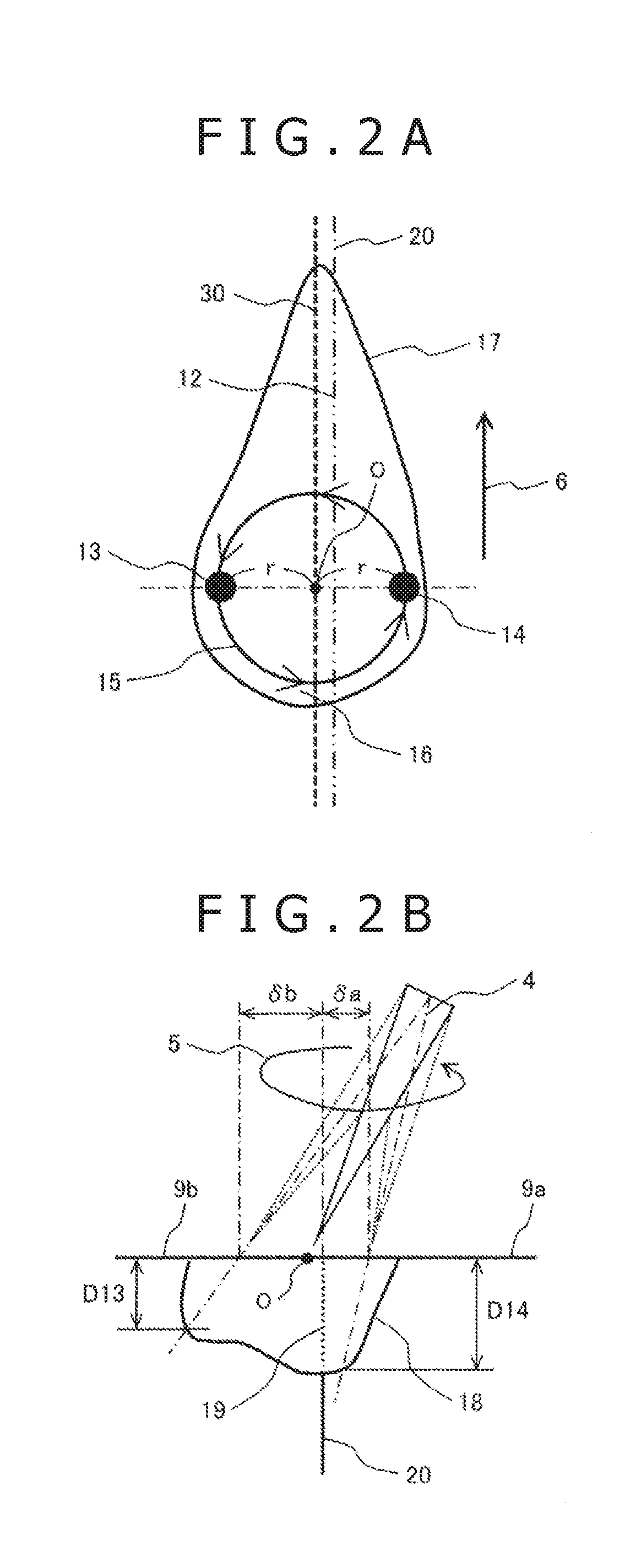
[0038]In FIG. 1, character 1 indicates a laser oscillator, character 2 indicates a laser optical fiber, character 3 indicates a galvanoscanner, character 4 indicates a laser beam, character 5 indicates a rotational direction of the laser beam, character 6 indicates a rotational direction of an object of welding (moving direction of the weld portion), character 7 indicates a shielding gas nozzle, character 8 indicates a shielding gas, character 9 indicates the object of welding, character 10 indicates a rotary spindle, character 11 indicates a processing stage, and character 24 indicates a control device.
[0039]In the present embodiment, the object of welding 9 is a fuel pump component, the material of which is 304 stainless steel. The laser beam 4 is a disk laser beam the wavelength of which is approximately 1030 nm. The scanning track of the laser beam 4 is a circle. The processing w...
embodiment 2
[0058]Embodiment 2 of the present invention will be described with reference to FIGS. 4 through 6B. In the drawings, the components that are the same as those of embodiment 1 are indicated by the same reference characters. A description of the components that are the same as those of embodiment 1 will be left out.
[0059]FIG. 4 is a schematic diagram illustrating a laser welding apparatus according to embodiment 2.
[0060]In the present embodiment, the object of welding 9A is different from that of embodiment 1. The object of welding 9A is a fuel injection part, and its material is 304 stainless steel. The laser beam 4 is a disk laser beam of a wavelength of approximately 1030 nm. The scanning track of the laser beam 4 is a circle. The laser beam 4 is applied from a direction perpendicular to the object of welding 9 to perform the processing. As in embodiment 1, the shielding gas 8 is nitrogen gas.
[0061]The object of welding 9A is fixed to a rotary spindle 10, and is rotated at a predet...
embodiment 3
[0072]Embodiment 3 of the present invention will be described with reference FIGS. 7 through 9B. In the drawings, the components that are the same as those of embodiments 1 and 2 are indicated by the same reference characters. A description of the components that are the same as those of embodiments 1 and 2 will be left out.
[0073]FIG. 7 is a schematic diagram illustrating a laser welding apparatus according to embodiment 3.
[0074]In the present embodiment, the object of welding 9B is different from that of embodiments 1 and 2. Since the object of welding 9B is different from that of embodiments 1 and 2, the arrangement of the rotary spindle 10B is different from that of embodiments 1 and 2. In embodiments 1 and 2, the rotation axis of the rotary spindle 10B is provided in the horizontal direction, whereas, in the present embodiment, the rotation axis of the rotary spindle 10B is provided in the vertical direction. The direction of the rotation axis of the rotary spindle 10B, however,...
PUM
| Property | Measurement | Unit |
|---|---|---|
| Length | aaaaa | aaaaa |
| Diameter | aaaaa | aaaaa |
| Ratio | aaaaa | aaaaa |
Abstract
Description
Claims
Application Information