Powered brake device

a brake device and power supply technology, applied in the direction of brake systems, mechanical equipment, transportation and packaging, etc., can solve the problems of reducing the effective proportion of magnetic flux that can contribute to torque generation, reducing the effective proportion of magnetic flux, and affecting the operation of the brake device, etc., to achieve quiet operation, reduce the effect of torque variation and high torque operation

Active Publication Date: 2018-07-12
NTN CORP
View PDF10 Cites 7 Cited by
  • Summary
  • Abstract
  • Description
  • Claims
  • Application Information

AI Technical Summary

Benefits of technology

[0011]An object of the present invention is to provide an electric brake device which can provide both a quiet operation with smaller torque variation for prioritizing NVH and a high torque operation or high output operation for prioritizing torque or output, by selectively using—based on requests—a control scheme that reduces torque variation and a control scheme that maximizes a torque.

Problems solved by technology

This may make it quite difficult to reduce the effects of torque variation through the use of controllers.
For example, the attempts to reduce torque variation by means of skewing or non-concentric geometry of magnets may generally result in the formation of complicated shapes and may decrease the effective proportion of magnetic flux that can contribute to torque generation.
Therefore, in order to nevertheless achieve a desired torque, issues like cost increase, size increase and weight increase may arise.
Also, the attempts to reduce torque variation by means of increased pole number may result in the increase of an electric angle per angular velocity of the motor due to the increased pole number.
Therefore, decreased responsiveness may be problematic at lower rotational frequencies.
Furthermore, a motor with smaller torque variation such as an induction motor can have a smaller torque density as compared with, for example, a brushless DC motor and therefore, its mountability may have to be sacrificed when size increase, weight increase and so on are inevitable.
However, at such an angle of the current phase, a torque to effective current may decrease, thus possibly leading to increased motor loss and consequently resulting in increased heat generation as well as increased power consumption.
Or, it may give rise to a possibility of decrease of the maximum torque that can be generated during energization with the maximum allowable level of current

Method used


Image

  • Powered brake device
  • Powered brake device
  • Powered brake device

Examples


Embodiment Construction

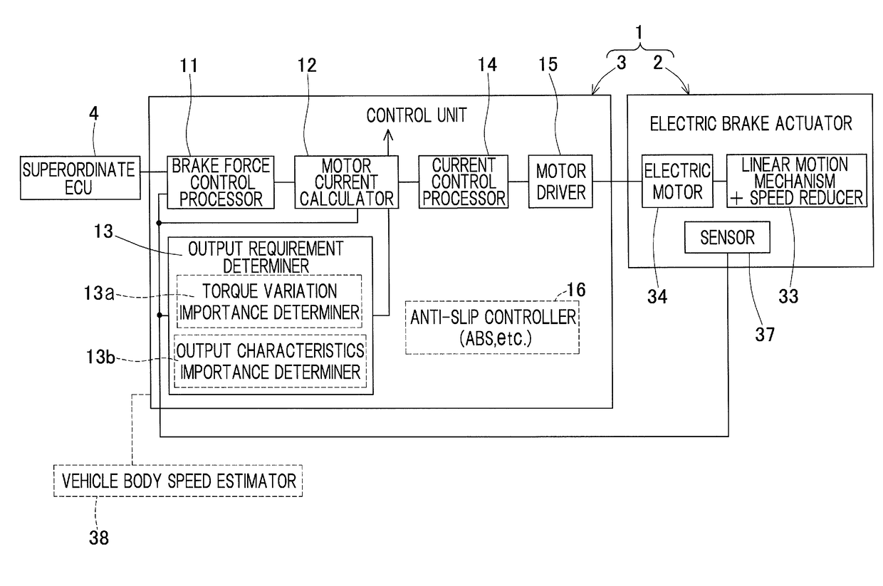
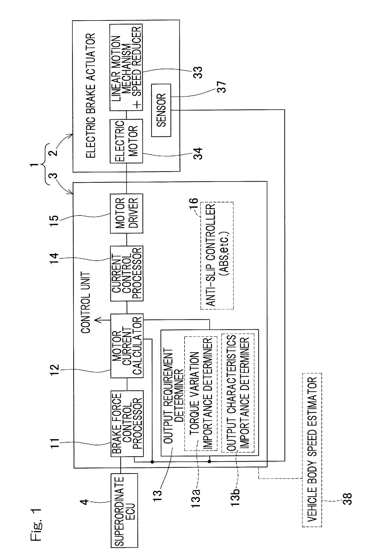
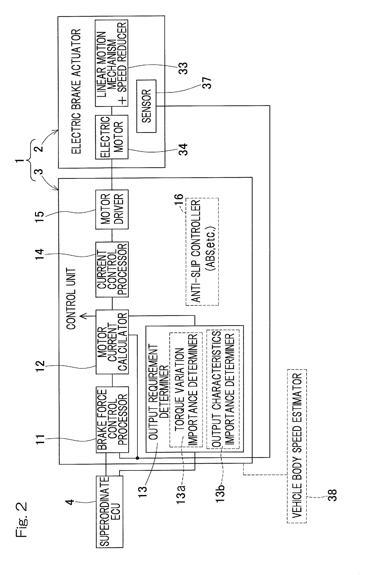
[0035]An embodiment of the present invention will be described in connection with the accompanying drawings. Referring to FIG. 1, an illustrated electric brake device 1 may include an electric brake actuator 2 that represents mechanical components thereof and a control unit 3 configured to control the electric brake actuator 2. The electric brake device 1 and a superordinate ECU 4 may cooperate to form an electric brake system. The superordinate ECU 4 may comprise an electronic control unit that can serve the function of generating a braking command based on an amount of operation—for example, depressing operation—of a brake operation unit (not shown) such as a brake pedal and of allocating the braking command among respective electric brake devices 1 on a vehicle. For example, the superordinate ECU 4 may take the form of a main ECU that can serve the function of performing cooperative control and / or supervisory control of the vehicle as a whole and of performing output control of a...


PUM


Abstract

Both of a quiet operation with smaller torque variation for prioritizing NVH and a high torque operation or high output operation for prioritizing torque or output may be provided by selectively using, based on requests, a control scheme that reduces torque variation and a control scheme that maximizes a torque. A motor current calculator may be capable of selectively using an output prioritizing control scheme that prioritizes a torque output and a torque variation suppressing control scheme that prioritizes smaller torque variation. An output requirement determiner may be provided to calculate a degree of importance of suppressing torque variation of an electric motor, based on one or both of a braking request and a travel condition of a vehicle. In accordance with this determination result, the motor current calculator may selectively use the output prioritizing control scheme and the torque variation suppressing control scheme.

Description

CROSS REFERENCE TO THE RELATED APPLICATION[0001]This application is a continuation application, under 35 U.S.C. § 111(a), of international application No. PCT / JP2016 / 076074, filed Sep. 6, 2016, which is based on and claims Convention priority to Japanese patent application No. 2015-178188, filed Sep. 10, 2015, the entire disclosure of which is herein incorporated by reference as a part of this application.BACKGROUND OF THE INVENTIONField of the Invention[0002]The present invention relates to a powered brake device or electric brake device to be installed to a vehicle such as an automotive vehicle.Description of Related Art[0003]The following designs have been proposed for an electric brake device:[0004](i) a design with an electric brake actuator that includes an electric motor, a linear motion mechanism and a reduction gear or speed reducer (see, for example, Patent Document 1); and[0005](ii) a design with an electric brake actuator that includes a planetary roller mechanism and an...

Claims


Application Information

Patent Timeline
Patent Type & Authority Applications(United States)
IPC IPC(8): B60T8/1761F16D65/18B60T8/172B60T8/32B60T13/74
CPCB60T8/1761F16D65/18B60T8/172B60T8/32B60T13/741F16D2121/24B60T13/74F16D66/00H02P27/00B60T8/173
Inventor MASUDA, YUI
Owner NTN CORP
Why Eureka
Try Eureka