

Vehicle door latch device
a technology for latching devices and vehicles, which is applied in the direction of electrical locking circuits, doors, and applications for locking, etc., and can solve the problem of longer operation time of electric motors operating in the door open direction
- Summary
- Abstract
- Description
- Claims
- Application Information
AI Technical Summary
Benefits of technology
Problems solved by technology
Method used
Image

Examples
Embodiment Construction
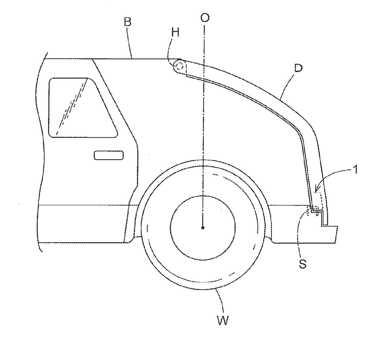
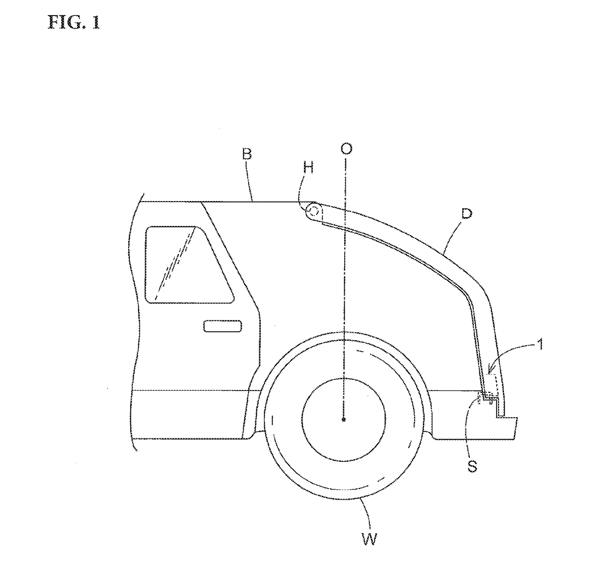
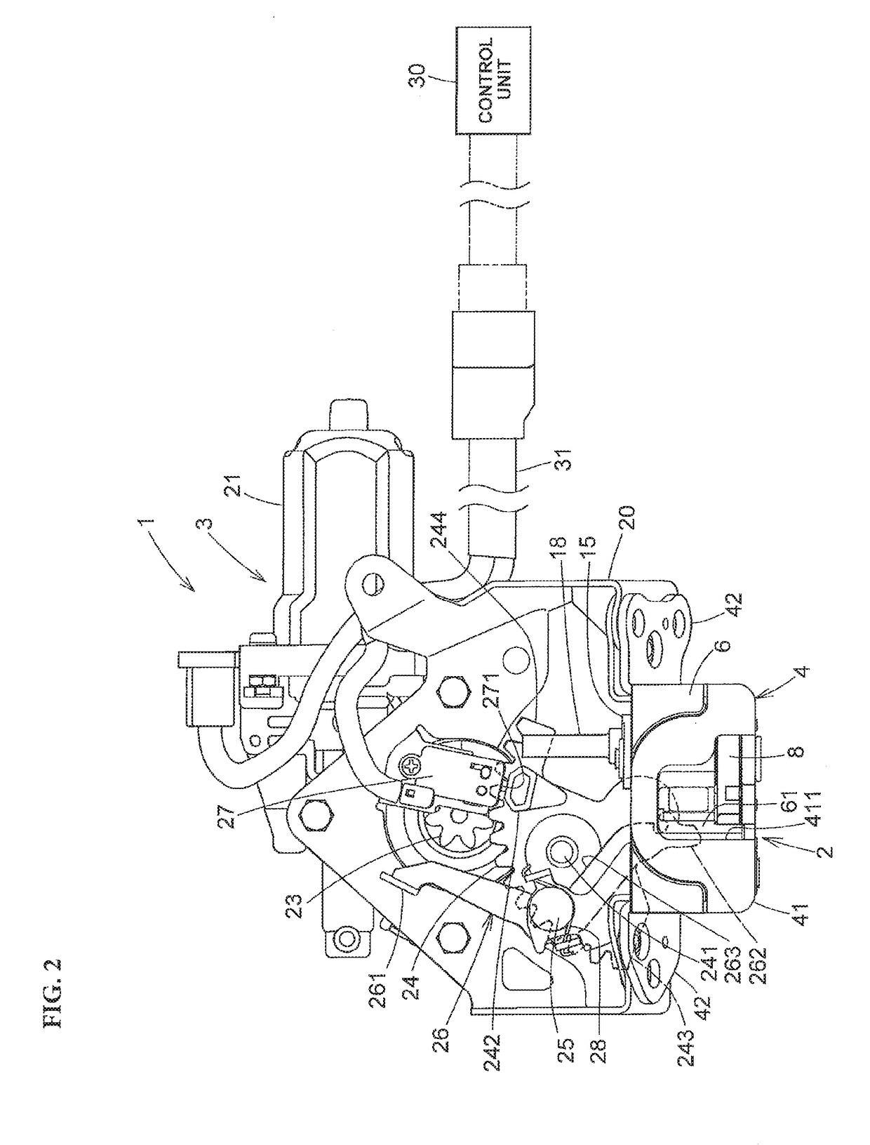
[0003]A door latch device for a vehicle provided on a back door comprises, for example, a base member fixed to the door; a latch which is pivotally mounted to the base member and is engageable with a striker on a vehicle body side; a ratchet which engages with the latch to prevents the rotation of the latch in the release direction, an open lever as a moving member which is movable in the release direction where engagement with the latch is canceled, a sector gear as the moving member which is, while enabling opening of the back door by moving the open lever in a release direction, capable of forcibly closing the back door to a completely closed state from the improperly closed state by moving the latch from a half-latch position to a full-latch position; an electric motor as an electrical drive source for driving the sector gear, a full-latch detecting switch for detecting a full-latch position of the latch, and a half-latch detecting switch for detecting a half-latch position of t...
PUM
 Abstract
Description
Claims
Application Information