

Conductive rubber roller
A rubber roller and rubber technology, applied in the field of transfer rollers of transfer printing components, can solve problems such as difficulty in achieving low resistance and small environmental dependence
- Summary
- Abstract
- Description
- Claims
- Application Information
AI Technical Summary
Problems solved by technology
Method used
Image

Examples
Embodiment 1-1 and comparative example 1-1 to 1-6
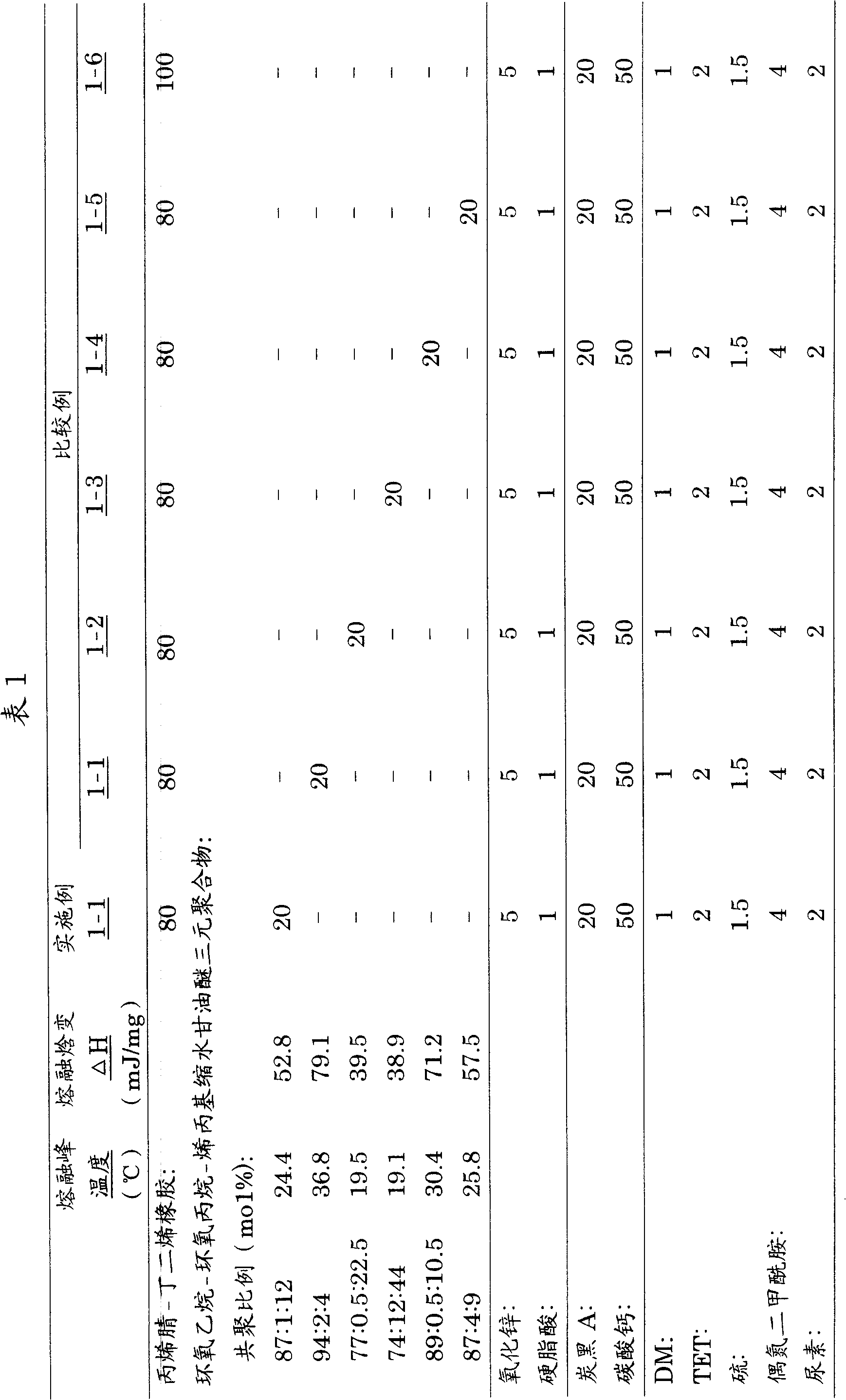
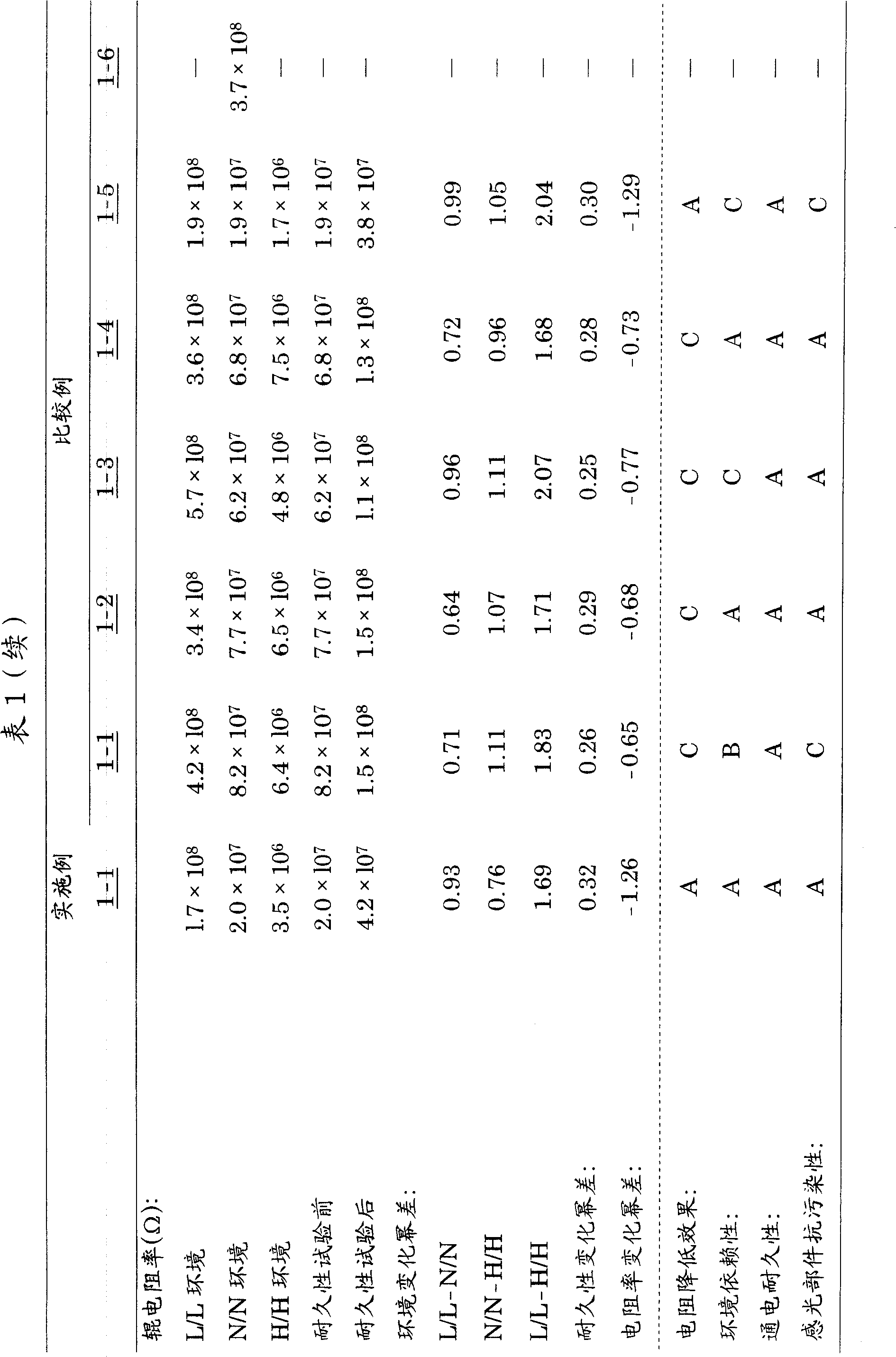
[0105] The results obtained are given in Table 1 together.
[0106] As shown in Table 1, it can be seen from Example 1-1 and Comparative Examples 1-1 to 1-5: ethylene oxide-propylene oxide-allyl glycidyl ether terpolymer is required in the present invention Is appropriate when it is within the range. More specifically, in Comparative Example 1-1, in which the melting peak temperature is higher and the melting enthalpy change ΔH is larger than those within the range of the present invention, and the copolymerization ratio of allyl glycidyl ether is smaller than the range of the present invention, Ethylene oxide has such high crystallization properties that it has a small resistivity reduction effect. At the same time, since the copolymerization ratio of allyl glycidyl ether is small, the obtained roller has great environmental dependence and poor resistance to contamination of the photosensitive member. In addition, in Comparative Example 1-2, in which the melting peak temperature ...
Embodiment 2-1 to 2-4 and comparative example 2-1
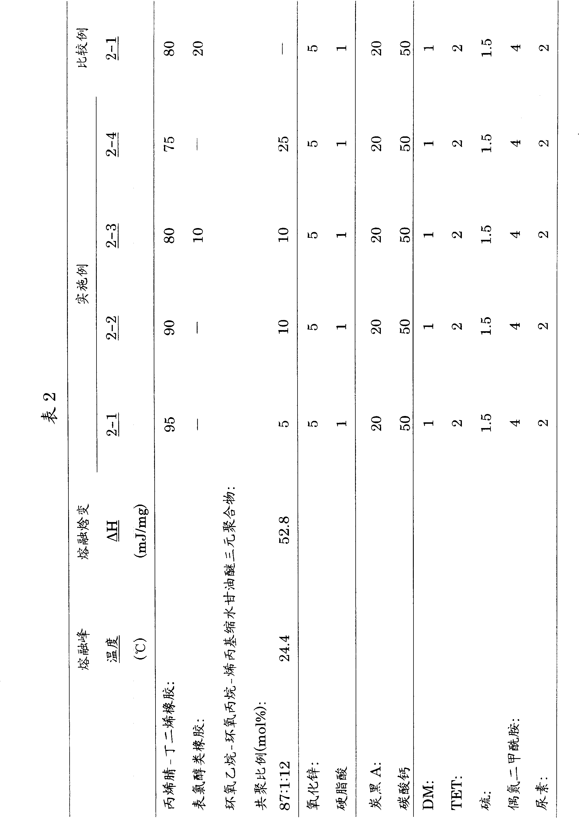
[0109] The test results obtained are given in Table 2 together.
[0110] As shown in Table 2, it can be seen from Examples 2-1 to 2-4 that the mixing amount of the ethylene oxide-propylene oxide-allyl glycidyl ether terpolymer used in the present invention is preferably 5 To 20 parts by mass. More specifically, in Example 2-4 in which the mixing amount thereof was greater than 20 parts by mass, the obtained conductive rubber roller showed large environmental dependence.
[0111] It can also be seen that, compared with Example 2-3, Comparative Example 2-1 shows that the resistance of the conductive rubber roller is not mixed with any ethylene oxide-propylene oxide-allyl glycidyl ether terpolymer. The conductive rubber roller controlled by only acrylonitrile-butadiene rubber and epichlorohydrin-based rubber shows a higher energization durability than the ethylene oxide-propylene oxide-allyl glycidyl ether ternary in accordance with the present invention. Poor polymer of Example 2-3....
Embodiment 3-1 and comparative example 3-1
[0113] The test results obtained are given in Table 3 together.
[0114] As shown in Table 3, it can be seen from Example 3-1 and Comparative Example 3-1 that the rubber composition used in the present invention more preferably contains an ion conductive agent. It is seen that Example 3-1, which is the same as Example 1-1 except for mixing 1 part by mass of the ion conductive agent, has achieved low resistivity more effectively, while retaining the small environmental dependence obtained in Example 1-1. In addition, no problem of contamination of photosensitive components was found. In contrast, for Comparative Example 3-1, in which 1 part by mass of the ion conductive agent was mixed into the rubber composition using the ethylene oxide-propylene oxide-allyl glycidyl ether terpolymer outside the scope of the present invention However, the effect of reducing the resistivity is insufficient, while the obtained roller has a large environmental dependence and further causes contaminat...
PUM
 Abstract
Description
Claims
Application Information