
Wireless Power Transmission Module

a power transmission module and wireless technology, applied in the direction of electrical apparatus construction details, transportation and packaging, differential interacting antenna combinations, etc., can solve the problems of inconvenient adjustment of the displacement between the coils, inconvenient working process, and inability to charge satisfactorily, so as to prevent the lowering of the charging efficiency and increase the assembly productivity , the effect of increasing the bonding property of the coils with other components

Active Publication Date: 2018-07-12
AMOSENSE
View PDF5 Cites 24 Cited by
  • Summary
  • Abstract
  • Description
  • Claims
  • Application Information

AI Technical Summary

Benefits of technology

The present patent improves the assembly and functionality of coils in electronic devices by using a supporting plate. The coils are fixed in place, preventing changes in their alignment and ensuring optimal charging efficiency. The supporting plate also has a heat radiating function, improving operational performance. Additionally, the material of the protective film attached to the supporting plate is replaced with a metal material to increase rigidity and enhance heat radiating performance. This results in a multifunctional member with improved performance and without increasing the overall thickness of the heat radiating plate.

Problems solved by technology

Further, at the time of being contacted or separated, fire may be caused due to instantaneous discharging phenomenon or the charging may not be satisfactorily performed due to contact failure.
Therefore, a working process is very inconvenient.
Further, when a failure in the alignment between the coils is found after completing the working process, it is very inconvenient to correct the displacement between the coils because the coils are bonded to each other.
However, the protective film of the related art is formed of a fluorine resin based material such as PET so that strength of the material is weak.
Therefore, the protective film may be torn or easily scratched due to an external impact.
Accordingly, the protective film may not satisfactorily perform a function as a protective film for protecting the heat radiating member.

Method used


Image

  • Wireless Power Transmission Module
  • Wireless Power Transmission Module
  • Wireless Power Transmission Module

Examples


Embodiment Construction

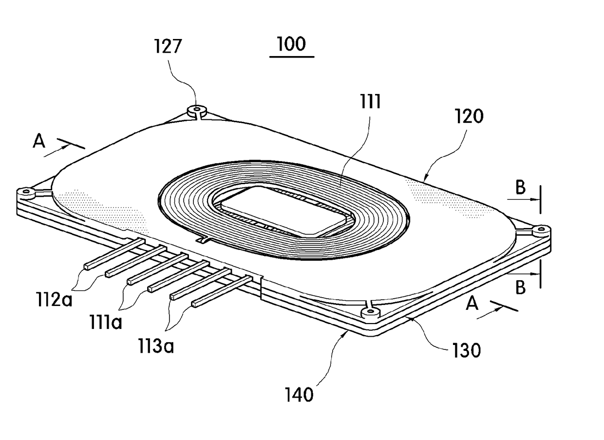
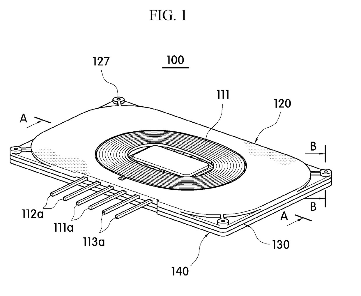
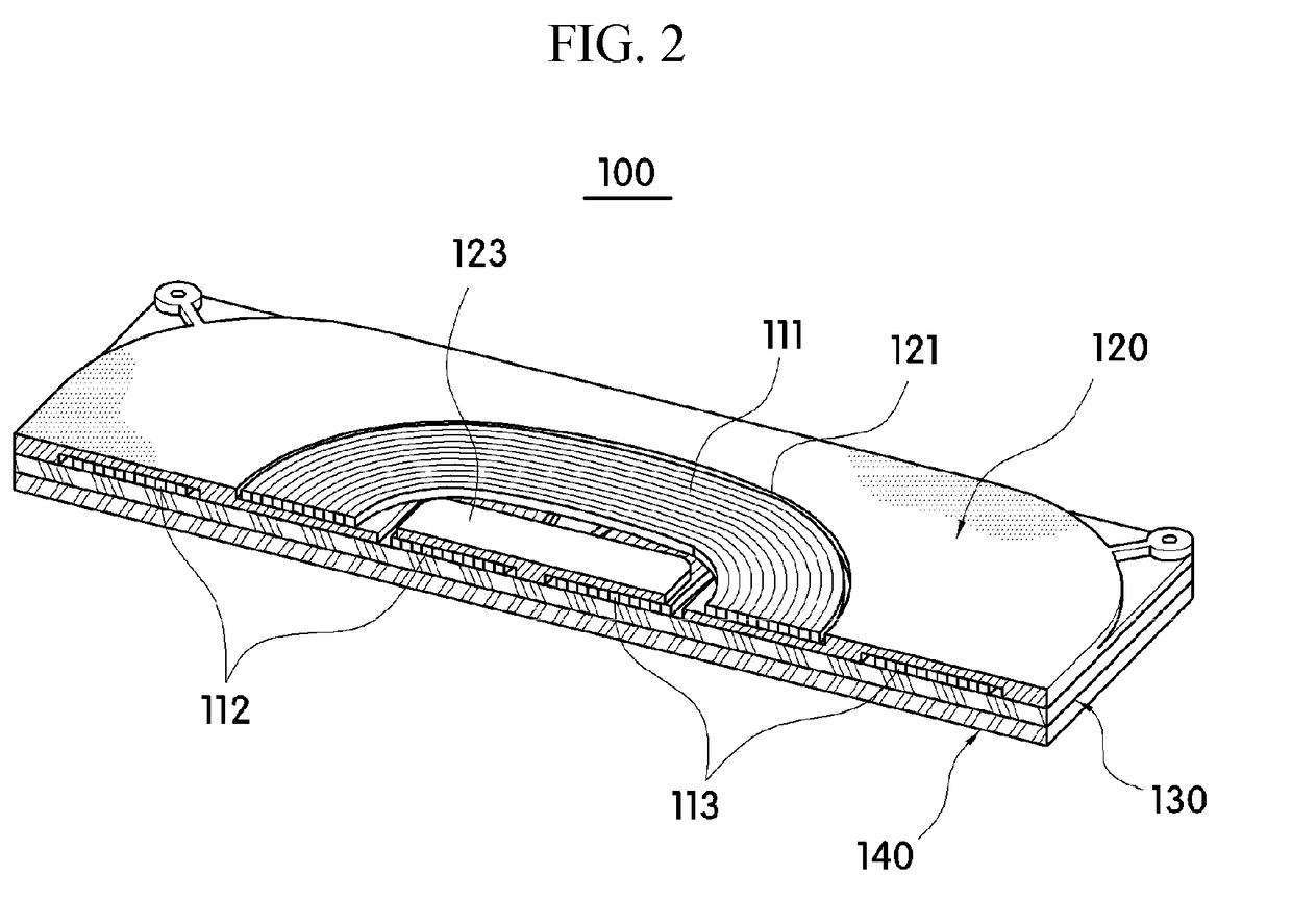
[0059]Hereinafter, exemplary embodiments of the present invention will be described more fully with reference to the accompanying drawings for those skilled in the art to easily implement the present invention. As those skilled in the art would realize, the described embodiments may be modified in various different ways and is not limited to the exemplary embodiments described herein. In the drawings, a part which is not related to the description is omitted to clearly describe the present disclosure. Further, like reference numerals designate like elements throughout the specification.

[0060]A wireless power transmission module according to an exemplary embodiment of the present disclosure may be embedded in electronic equipment such as a portable terminal including a smart phone. The wireless power transmission module may transmit wireless power to a wireless power reception module which is electrically connected to a battery to charge the battery included in the electronic equipme...


PUM


Abstract

A wireless power transmission module is provided. According to an exemplary embodiment of the present disclosure, a wireless power transmission module includes an antenna unit, a magnetic field shielding sheet, and a planar heat radiating plate. The antenna unit includes at least one wireless power transfer antenna. The magnetic field shielding sheet shields a magnetic field generated by the antenna unit to suppress external leakage of the magnetic field and concentrate the magnetic field in a desired direction. The planar heat radiating plate which is disposed on one surface of the magnetic field shielding sheet to release heat generated by the antenna unit. The wireless power transmission module is equipped or embedded in a vehicle to be used to charge a main battery of a portable terminal.

Description

CROSS-REFERENCE TO RELATED APPLICATION[0001]This application claims priority under 35 USC § 119 to Korean Patent Application No. 10-2015-0102523 filed on Jul. 20, 2015 in the Korean Intellectual Property Office (KIPO), the disclosure of which is incorporated by reference herein in its entirety.BACKGROUNDTechnical Field[0002]The present disclosure relates to a wireless power transmission system, and more particularly, to a wireless power transmission module which wirelessly supplies power to charge batteries of electronic devices.Discussion of the Related Art[0003]Recently, usage of electric devices with a battery which is charged by external power, for example, usage of a mobile terminal, such as a portable phone, a smart phone, a tablet personal computer (PC), a notebook computer, a digital broadcasting terminal, a personal digital assistant (PDA), a portable multimedia player (PMP), or a navigation system, is increasing.[0004]Therefore, surrounding environments related with the us...

Claims


Application Information

Patent Timeline
IPC IPC(8): H02J7/02H01F38/14H01Q7/00H05K9/00H05K3/28H05K7/20H02J50/12
CPCH02J7/025H01F38/14H01Q7/00H05K9/00H05K3/281H05K7/20472H02J50/12H02J5/005H02J50/80H01F27/22H01Q21/29H02J7/0042H02J50/10H02J50/70H01F27/36H01F27/366H04B5/43H02J2310/22
Inventor HWANG, SEUNG JAEJANG, KIL JAE
Owner AMOSENSE
Learn More