Projection device and method for projection comprising optical free-form surfaces

a projection device and free-form surface technology, applied in the direction of picture reproducers, lighting and heating apparatus, instruments using projection devices, etc., can solve the problems of considerable power efficiency loss, limited resolution in light distribution generation for realistic source distribution, and application of this type of free-form redistribution exhibit considerable deficiencies, so as to reduce the lossy fading of light, improve the power transmission of optics, and improve imaging quality

Active Publication Date: 2018-07-12
FRAUNHOFER GESELLSCHAFT ZUR FOERDERUNG DER ANGEWANDTEN FORSCHUNG EV
View PDF1 Cites 11 Cited by
  • Summary
  • Abstract
  • Description
  • Claims
  • Application Information

AI Technical Summary

Benefits of technology

[0031]Simply using a light-redistributing free-form surface in the array projector is of little use. Additionally, it is of advantage to use at least two free-form surfaces which are coupled in their effects.
[0032]In accordance with embodiments, the beam shaper/projection unit is compact ultra-thin optics (A) having a large light flux (B) at the same time. Both smooth/coarsely patterned light distributions can be generated by free-form light redistribution, and very fine high-resolution light patterns having nearly any contrasts desired can be generated by combining the free-form light redistribution and transmission-modulated structures (D). By applying the free-form light redistribution, the power transmission of the optics can be improved considerably (C). With very fine high-resolution target light patterns, a real light pattern within the optics is generated by the free-form light redistribution, which is very well adapted to the transmission-modulated structures (like apertures) and thus reduces the lossy fading of light strongly. With less fine target light distributions, the lossless free-form light redistribution can be applied exclusively and the transmission-modulated structures rather serve for scattering and stray light minimization. It has to be emphasized in particular here that the pattern smearing/blurring described under (ii) in conventional free-form light redistribution can be reduced very strongly by our nove

Problems solved by technology

However, light is faded out by absorptive slides or dynamics imagers, for example, which may result in a considerable loss in power efficiency (C).
However, applying this type of free-form redistribution exhibits considerable deficiencies.
However, the by large greatest deficiency is the limited resolution in light distribution generation for realistic source distributions [Zwick].
However, the problem of a potentially low power efficiency or system transmission is still present.
By absorbing or fading light as a consequence of object patterns to be imaged, considerable transmission losses may arise.
Considerable losses result, for example, when generating grey scale profiles having strong irradiation intensity maximums, when forming narrow light pattern features on a less bright or even lacking background illumination or when generating non-trivial boundaries of the real or virtual region to be illuminated.
Well-known single-channel projectors or illumination configurations consequently exhibit the disadvantages that a miniaturization of the projectors/illumination configurations entails a reduction of the light flux transmissibl

Method used


Image

  • Projection device and method for projection comprising optical free-form surfaces
  • Projection device and method for projection comprising optical free-form surfaces
  • Projection device and method for projection comprising optical free-form surfaces

Examples


Embodiment Construction

[0058]Same elements or elements of equal effect will be provided with same reference numerals in the following description of the figures so that the description thereof is mutually exchangeable between the different embodiments.

[0059]In accordance with embodiments, the object of the invention is providing an ultra-thin high-efficiency optical element for generating patterned illumination or for a projection with a potentially large light flux, wherein additionally a homogenization effect / color mixture of the source radiation takes place. Light distributions on real and / or virtual targets having most different structural features (like fine patterns of high resolution, high contrasts etc.) are to be made possible.

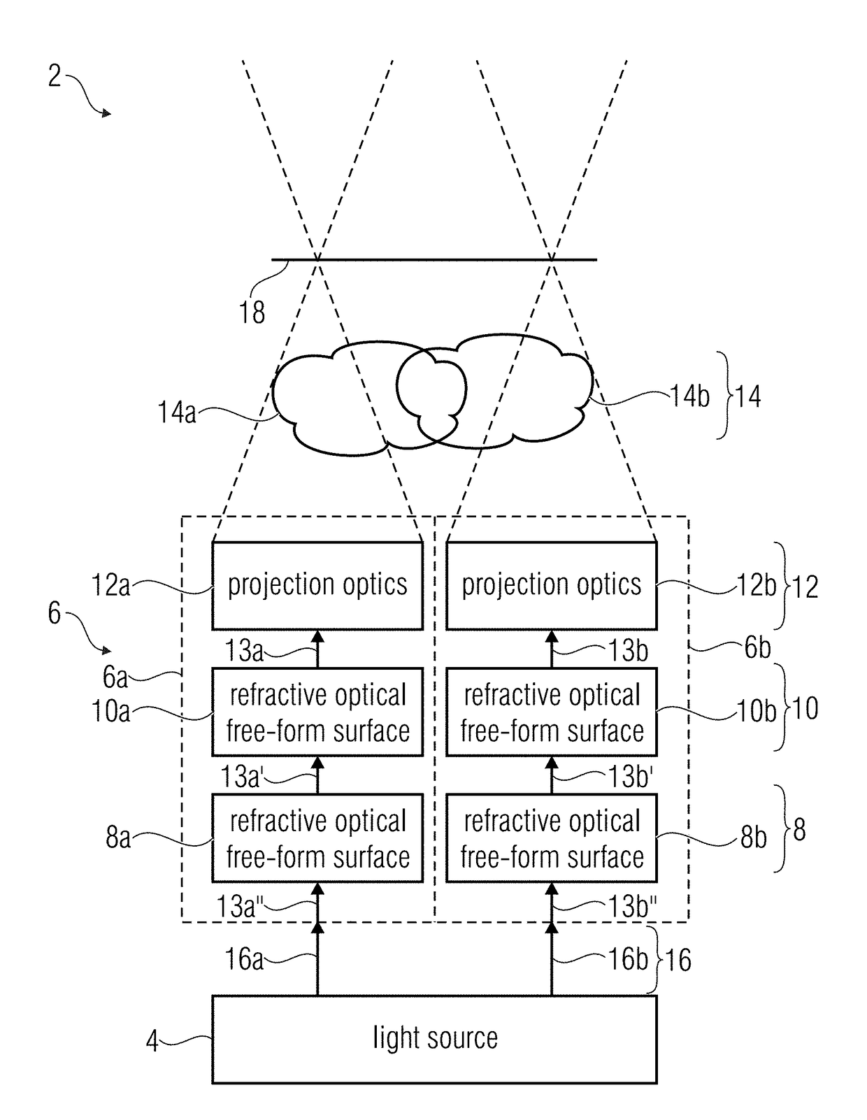
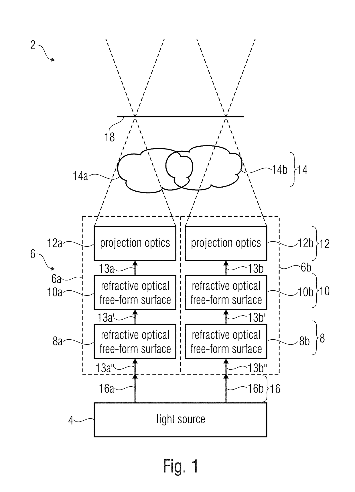
[0060]FIG. 1 shows a schematic block diagram of a projection device 2 comprising at least one light source 4 and an array of optical channels 6, 6a, 6b. Each channel comprises a first refractive optical free-form surface 8a, 8b and a second refractive optical free-form surf...


PUM


Abstract

What is shown is a projection device having at least one light source and an array of optical channels. Each channel includes a first refractive optical free-form surface and a second refractive optical free-form surface and projection optics. The first and second refractive optical free-form surfaces are arranged between the light source and the projection optics and cause Köhler illumination of the projection optics by an object light pattern, resulting in the image to be projected on an image surface of the projection optics, wherein images of the array of optical channels superimpose one another.

Description

CROSS-REFERENCE TO RELATED APPLICATIONS[0001]This application is a continuation of co-pending International Application No. PCT / EP2016 / 070490, filed Aug. 31, 2016, which is incorporated herein by reference in its entirety, and additionally claims priority from German Application No. 10 2015 216 985.5, filed Sep. 4, 2015, which is also incorporated herein by reference in its entirety.[0002]The present invention relates to a projection device and to a method for projecting having refractive optical free-form surfaces. Embodiments exhibit a free-form array projection. In accordance with embodiments, the free-form surfaces generate Köhler illumination of projection optics of the projection device by an object light pattern.BACKGROUND OF THE INVENTION[0003]The beam shaper / projection unit may be employed when generating any structured illumination in many fields of application, like background and accentuating illumination in general illumination, generating defined radiation profiles for...

Claims


Application Information

Patent Timeline
IPC IPC(8): H04N9/31G02B27/09G02B27/00
CPCH04N9/3152G02B27/0955G02B27/0927G02B27/0025G03B21/13F21W2121/00G02B3/0056G02B27/18F21W2103/60G03B21/206
Inventor MICHAELIS, DIRKSCHREIBER, PETER
Owner FRAUNHOFER GESELLSCHAFT ZUR FOERDERUNG DER ANGEWANDTEN FORSCHUNG EV
Why Eureka
Try Eureka