Method and device for producing a 3-d substrate coated with a laminate

a technology of laminate and 3d substrate, applied in the field of 3d substrate production, to achieve the effect of facilitating a cycle time of less

Active Publication Date: 2018-07-26
LEONHARD KURZ STIFTUNG & CO KG
View PDF3 Cites 5 Cited by
  • Summary
  • Abstract
  • Description
  • Claims
  • Application Information

AI Technical Summary

Benefits of technology

[0021]Improving upon the art recited supra it is an object of the invention to provide a method for coating a 3D-substrate with a laminate that is suitable for commercial or industrial applications and that facilitates a cycle time of less than 120 seconds, more advantageously of less than 60 seconds. Additionally a compact and efficient device shall be provided for performing the method.

Problems solved by technology

Through this method also undercuts at the substrate can be coated and recesses and pockets in the substrate surface can be lined which was not possible with prior decorating methods.

Method used


Image

  • Method and device for producing a 3-d substrate coated with a laminate
  • Method and device for producing a 3-d substrate coated with a laminate
  • Method and device for producing a 3-d substrate coated with a laminate

Examples


embodiment 1

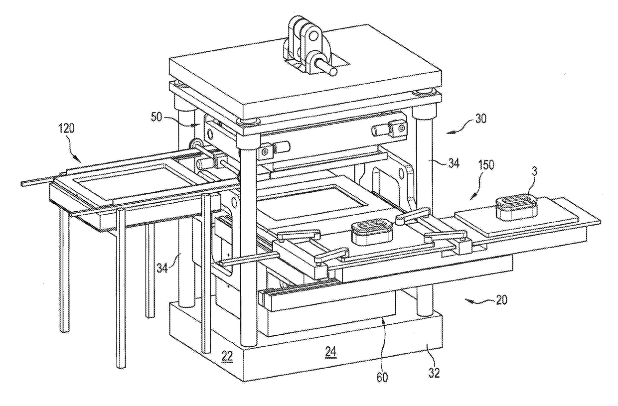
[0231]A forming tool is used as illustrated in FIGS. 2-5 and described supra in detail.

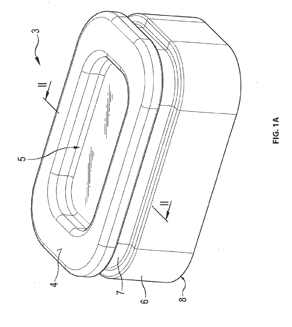
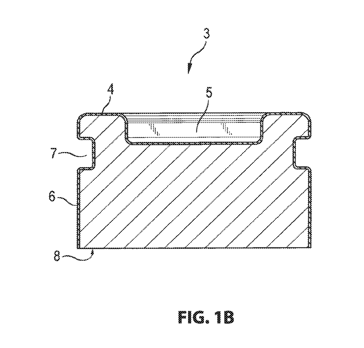
[0232]A 3D-substrate is used as illustrated in FIGS. 1A and 1B and described supra in detail.

[0233]The 3D-Substrate is firmly attached on a rectangular carrier plate. The carrier plate has dimensions of 530 mm×350 mm and is made from polyimide. The carrier plate is coated with TEFLON®.

[0234]A 1 mm thick structured foil made from a blend of TPU and PMMA which is died solid black is used for a laminate wherein the structured foil is provided with a diamond structure on its visible side by negative printing. A structured foil of this type is sold by EXEL GMBH, 81301 Rohrdorf, Del.

[0235]DESMOMELT 530 sold by Bayer Material Science is used as a glue. This is a granular product that is thermally activate able at or above 75° C. the granulate is processed in an extruder into a pre plasticized melt which is applied by a slotted nozzle on the contact side of the structure foil in a limited surface section ...

embodiment 2

[0246]The embodiment according to claim 1 is essentially repeated. As a difference therefrom a blank made from the structured foil recited supra is used which is provided at its contact side on its entire surface with a dry layer made from the same glue. This glue has a size which corresponds essentially to the cover able surface at the 3D-Substrate. This blank adheres by an adhesion glue that can be removed without residuals at a piece of transfer foil. A standard PP foil with a layer thickness of 300 μm is used as a transfer foil. The transfer foil piece has dimensions so that it can be clamped between the transport frame at the pressure bell and the intermediary frame at the tool trough.

[0247]The evacuation, heating, loading with high pressure fluid, subsequent ventilation of the spaces, cooling of the product and moving the product out of the forming tool are performed under the stated conditions. At the product the coated body includes an edge strip with excess structure foil w...


PUM

PropertyMeasurementUnit
pressureaaaaaaaaaa
pressureaaaaaaaaaa
thicknessaaaaaaaaaa

Abstract

A forming tool is used, which has a tool trough arranged in a stationary manner and a pressure bell, which can be lowered onto and lifted away from the tool trough. An arrangement is created in which a single- or multi-layer, initially flat, flexible laminate separates the trough interior from the pressure-bell interior in a pressure tight manner. A table, on which the 3-D substrate to be coated is located, assumes a lowered position within the trough interior; there is a considerable, free intermediate space (between the laminate and the 3-D substrate. A radiant-heater assembly is inserted into said intermediate space. The radiant-heater assembly has a carrier, on the top side of which radiant heaters that can be activated are attached and on the bottom side of which radiant heaters that can be activated are attached.

Description

RELATED APPLICATIONS[0001]This application is a continuation of International Application PCT / EP2016 / 001536 filed on Sep. 12, 2016 claiming priority from German Application DE 10 2015 012 242.8 filed on Sep. 18, 2015, both of which are incorporated by their entirety by this reference.FIELD OF THE INVENTION[0002]The instant invention relates to a method for producing a 3D-substrate that is coated with a laminate. The invention furthermore relates to a device for performing the method.[0003]The term 3D-substrate designates an element with a three dimensional surface contour. The laminate can be configured with one layer or with plural layers. A typical advantageous laminate includes at least one plastic foil which can be e.g. made from Polycarbonate (PC), Acrylnitril-Butadien-Styrol-Terpolymeres (ABS), PC / ABS-blends, Poly(meth)acrylate (PMMA), Polyester (PE), Polyamide (PA), Polypropylene (PP), Polyarylsulfon (PSU) or Polyvinylchloride (PVC).[0004]Coating with a laminate of this type ...

Claims


Application Information

Patent Timeline
Patent Type & Authority Applications(United States)
IPC IPC(8): B29C51/16B29C51/10B29C65/48B29C65/00B29C51/14B29C51/20B29C51/26B29C51/38B29C51/42
CPCB29C51/165B29C51/10B29C65/4845B29C65/4835B29C66/00145B29C66/301B29C51/14B29C51/20B29C51/261B29C51/38B29C51/425B29C2791/006B29K2677/00B29K2075/00B29K2033/12B29K2105/256B29K2105/0097B29L2009/005B29L2031/3005B29C51/12B29C51/18B29C2791/007
Inventor DREXLER, CHRISTIAN
Owner LEONHARD KURZ STIFTUNG & CO KG
Why Eureka
Try Eureka