Process and apparatus for controlled exposure of flexographic printing plates and adjusting the floor thereof

a technology of flexographic printing and controlled exposure, which is applied in the direction of electrical equipment, printed circuit manufacture, instruments, etc., can solve the problems of unsatisfactory variability in plate quality, more susceptible to damage during use, and still not optimal, so as to reduce the delay time and improve the stability of the dots

Active Publication Date: 2018-07-26
ESKO GRAPHICS IMAGING
View PDF2 Cites 43 Cited by
  • Summary
  • Abstract
  • Description
  • Claims
  • Application Information

AI Technical Summary

Problems solved by technology

This variability in elapsed time between first and second exposure leads to undesirable variability in plate quality.
Still other processes may include exposing both the back side and the front side of a plate simultaneously, which although it produces more predictable results than a process that imposes a variable time delay, is still not optimal, as discussed more herein later.
In the field of printing, minimizing the size of a dot printed on a substrate is desirable, but smaller dots correspond to smaller printing plate elements, which are more susceptible to damage during use.

Method used


Image

  • Process and apparatus for controlled exposure of flexographic printing plates and adjusting the floor thereof
  • Process and apparatus for controlled exposure of flexographic printing plates and adjusting the floor thereof
  • Process and apparatus for controlled exposure of flexographic printing plates and adjusting the floor thereof

Examples


example

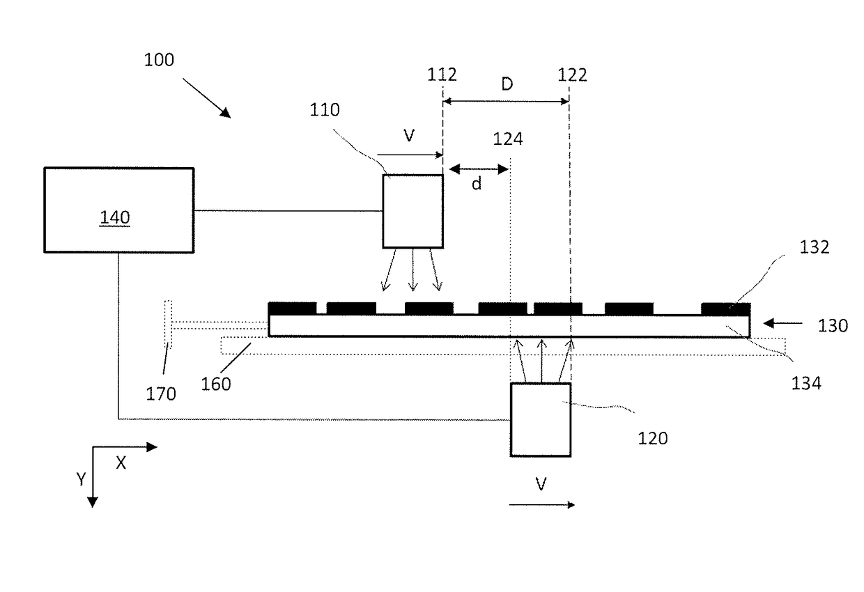
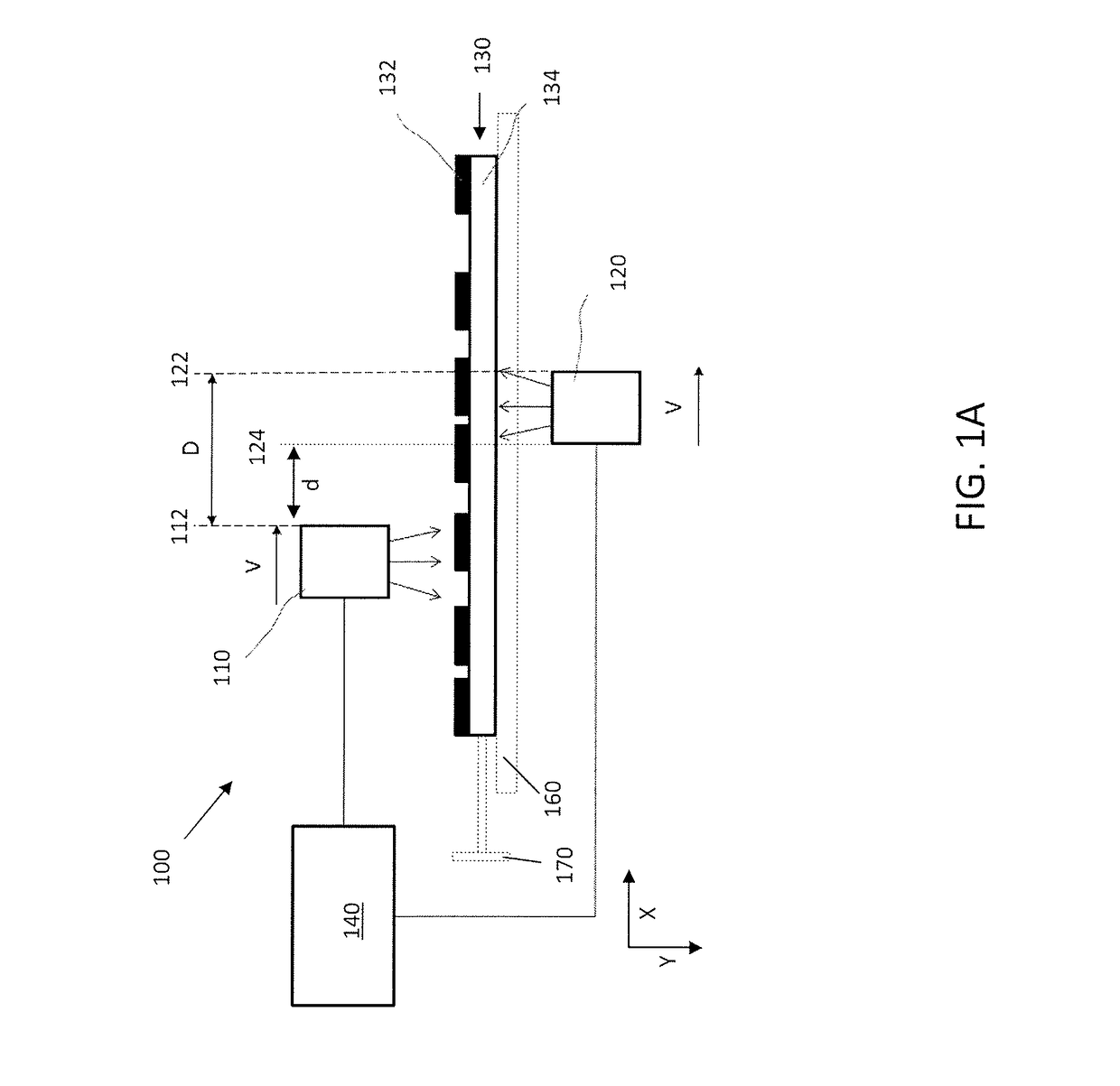
[0043]For optimization of the time delay, single element structures of various sizes were imaged by a laser into the mask of a photosensitive printing plate at a resolution of 4000 dpi. For this example, a Model No. DPR 045 printing plate, manufactured by DuPont, was used.

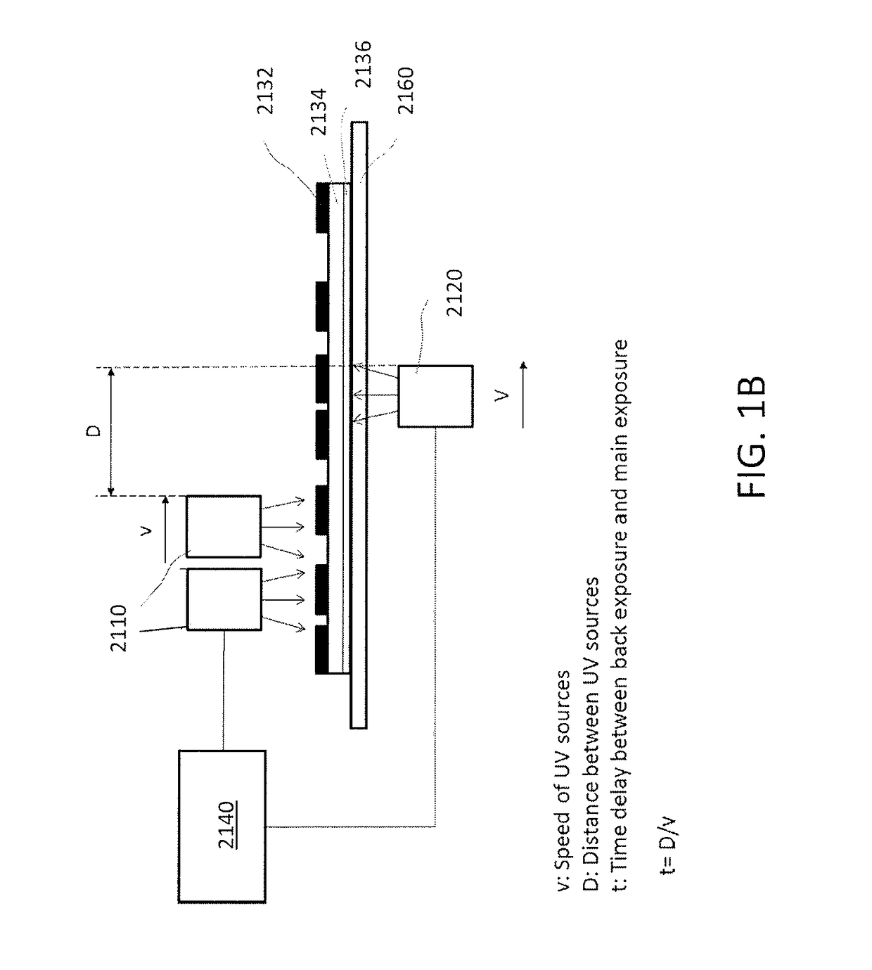
[0044]The photosensitive printing plates were then back exposed, such as by using UV radiation source 120, and main exposed, such as by using UV radiation source 110, as depicted in FIG. 1. For this example, each source 120 and 110 source comprised a linear source comprising a bank of individual LED UV point sources, as described in more detail herein. The plate was exposed in a single exposure step using a main side UV irradiance of 230 mw / cm2 at a wavelength of 360 nm and a back side UV irradiance of 17 mw / cm2 at the same wavelength at a relative plate speed of 1.25 mm / sec. For this example, the UV radiation sources were moved lengthwise under and above the surface of each photosensitive printing plate at the spe...


PUM

PropertyMeasurementUnit
speedaaaaaaaaaa
wavelengthaaaaaaaaaa
diameteraaaaaaaaaa

Abstract

A method and apparatus to expose photosensitive printing plates with a predetermined radiation density from the main side (top) and a predetermined radiation density from the back side (bottom). The method comprises executing the main exposure with a time delay after the back exposure. The time delay between back exposure and main exposure is optimized to create smaller stable single dot elements on the photosensitive printing plate after processing and smaller single element dot sizes printed on the print substrate. The plate floor may be adjusted by performing a back-side-only exposure prior to executing the combined back and main exposure with the time delay.

Description

CROSS-REFERENCE TO RELATED APPLICATIONS[0001]This application is a continuation-in-part of PCT Application Ser. No. PCT / IB2016 / 001660, titled SYSTEM AND METHOD FOR CONTROLLED EXPOSURE OF FLEXOGRAPHIC PRINTING PLATES, filed 26 Oct. 2016, which claims priority to U.S. Provisional Patent Application Ser. No. 62 / 246,276, filed on 26 Oct. 2015. This application also claims priority to U.S. Provisional Application Ser. No. 62 / 473,784, titled “PROCESS AND APPARATUS FOR ADJUSTING THE FLOOR OF A FLEXOGRAPHIC PRINTING PLATE IN A CONTROLLED EXPOSURE SYSTEM OR PROCESS,” filed 20 Mar. 2017. All of the foregoing are incorporated herein by reference in their entireties.BACKGROUND OF THE INVENTION[0002]Many processes are known in the art for preparing polymer printing plates, such as photopolymer flexographic plates and letterpress printing plates coated with photopolymer material. One known process starts with a plate having an ablatable material thereon, imaging the plate in a digital imager to a...

Claims


Application Information

Patent Timeline
Patent Type & Authority Applications(United States)
IPC IPC(8): G03F7/20H05K3/00
CPCG03F7/201G03F7/203G03F7/2032H05K3/0082G03F7/2004G03F7/24
Inventor WOLTERINK, JORGHANSEL, THOMASSIEVERS, WOLFGANG
Owner ESKO GRAPHICS IMAGING
Why Eureka
Try Eureka