
Semi-solid flow li/o2 battery

a flow li/o2 battery, semi-solid technology, applied in batteries, fuel and secondary cells, electrode carriers/collectors, etc., can solve the problem of limited capacity of cells, and achieve the effect of reducing the discharge capacity of cathodes

Active Publication Date: 2018-08-09
ALMA MATER STUDIORUM UNIV DI BOLOGNA
View PDF0 Cites 4 Cited by
  • Summary
  • Abstract
  • Description
  • Claims
  • Application Information

AI Technical Summary

Benefits of technology

This patent describes a new type of battery called a lithium oxygen battery that uses a semi-solid catholyte with electrolyte, dissolved oxygen, and carbon particles. The catholyte can flow and is saturated with oxygen. The carbon particles are insoluble in the catholyte and can be made of conductive carbon black. The patent also describes a lithium oxygen battery for use in electric vehicles and stationary plants. The technical effects of this battery are increased energy density, improved cycling efficiency, and reduced cathode resistance.

Problems solved by technology

The authors of the paper postulate that the capacity of the cell would be limited by the size of the gas diffusion tank.

Method used


Image

  • Semi-solid flow li/o2 battery
  • Semi-solid flow li/o2 battery
  • Semi-solid flow li/o2 battery

Examples


example 1

ry Study

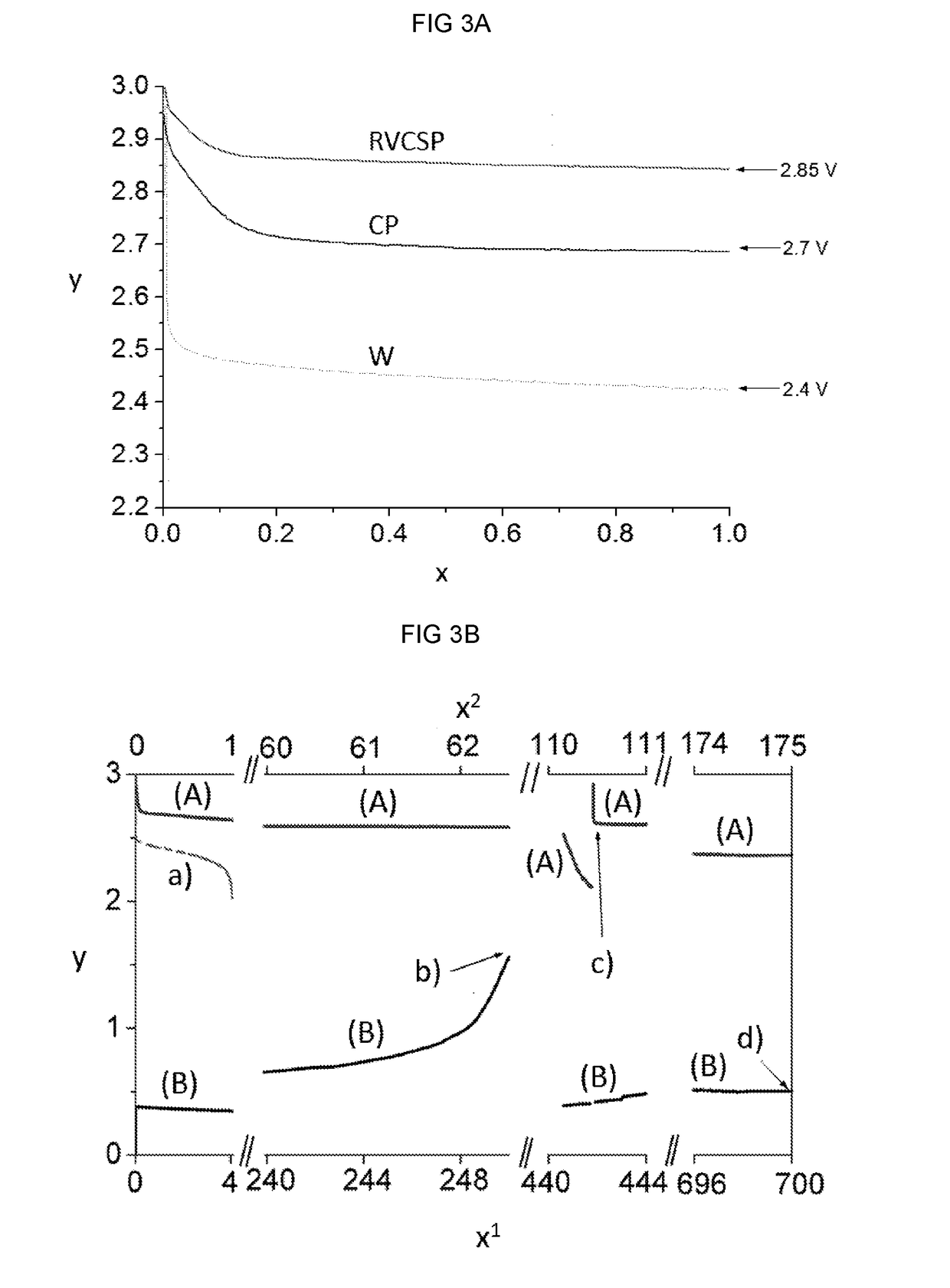
[0094]An experiment was performed in a 5 mL conventional electrochemical cell using electrolyte (TEGDME:LiTFSI 9:1 mol, LiTFSI concentration ca. 0.5 mol / L) or catholyte (TEGDME:LiTFSI 9:1 mol, 2% wt. SP). The electrolyte or catholyte were continuously fed with oxygen and were mechanically stirred to simulate flow cathode operative conditions. The porous cathode current collectors used were CP or RVCSP. A lithium counter electrode (separated by the cathode compartment via a porous frit) and an Ag-based reference electrode were used. The lithium counter electrode was a lithium foil (ca. 1×5 cm2) which was rolled around a glass rod and featured an area which was 10 times higher than that of the working electrode. Such approach was used for the basic studies in order to not limit working electrode operation.

[0095]The results reported in FIG. 3 show that under galvanostatic discharge at 0.25 mA / cm2 when the catholyte containing SP (Super-P) was used in the cell, the CP discharge ...

example 2

xygen Battery

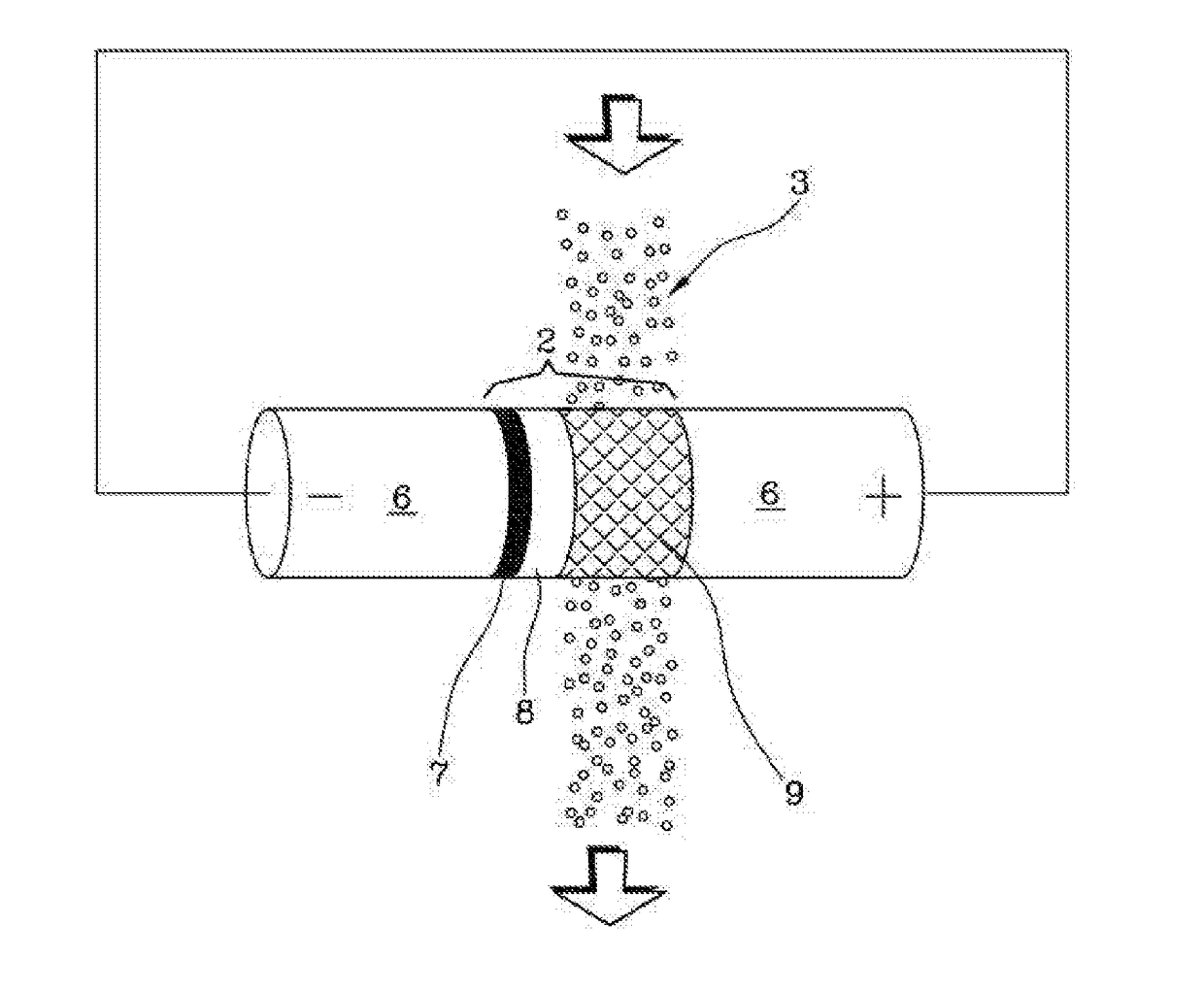
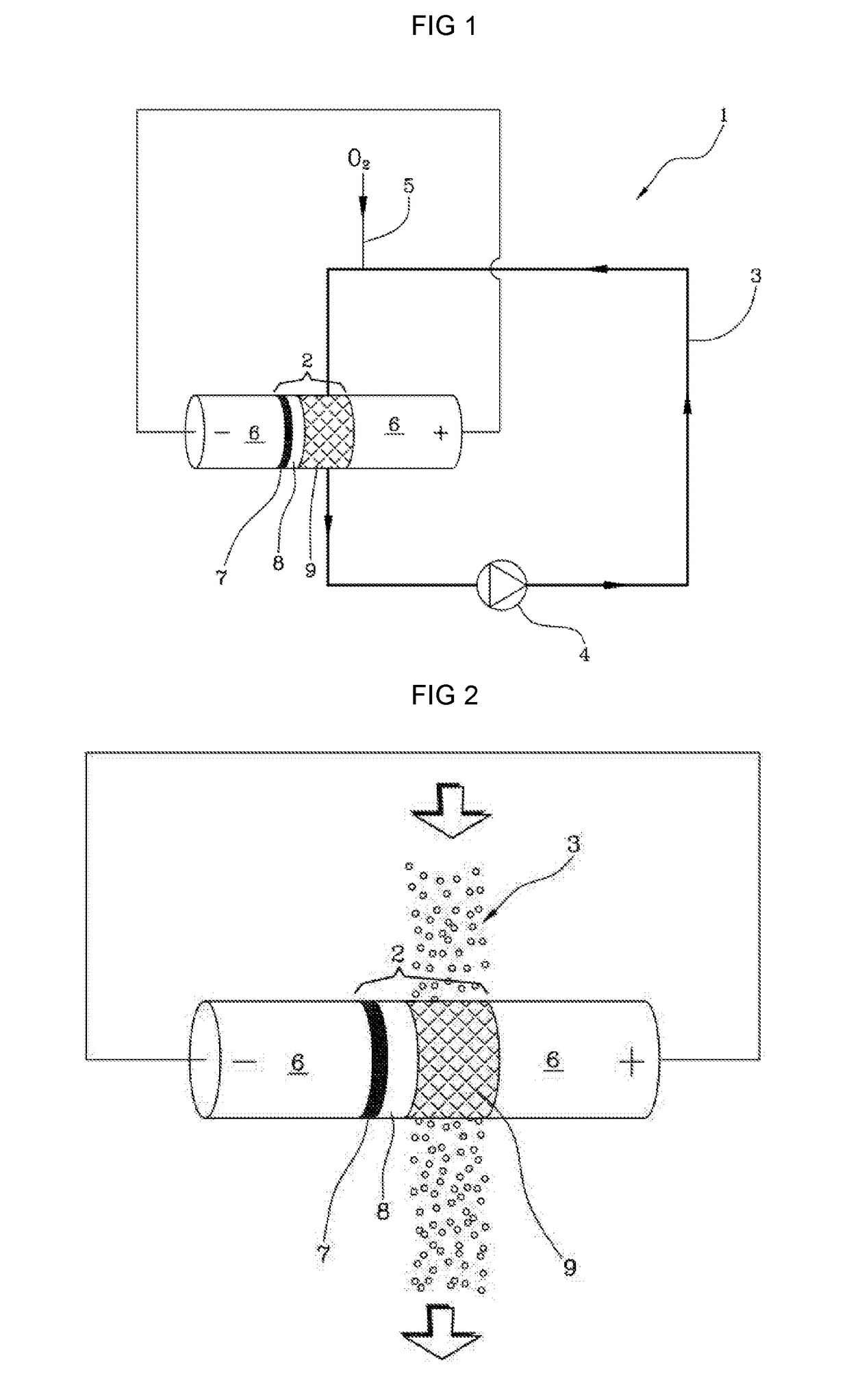
[0099]A macroporous RVC current collector was coated with SP (SEM image, FIG. 7) (0.385 cm2, 7 mg cm−2 of SP). The RVCSP current collector was used to assemble the semi-solid, flow Li / O2 cell which is schematized in FIGS. 1 and 2. The cell core constituted a lithium metal anode and a RVCSP current collector separated by a fibreglass membrane. The catholyte was pumped through the cell by a peristaltic pump while being continuously enriched with O2 (g). For basic studies, an additional reference electrode which intercepted the catholyte flow was used (not reported in FIGS. 1 and 2).

[0100]Polarization tests were carried out on the prototype consisting in the repetition of 1 hour discharge steps at different current densities from 0.05 mA cm−2 up to 4 mA cm−2. The sequence was stopped when the cathode potential was lower than 2 V vs. Li+ / Li or the anode potential was higher than 1 V vs. Li+ / Li. The pump rate was 200 rpm which corresponded to a catholyte flow of approximatel...


PUM

PropertyMeasurementUnit
current densitiesaaaaaaaaaa
flow rateaaaaaaaaaa
flow rateaaaaaaaaaa

Abstract

The present disclosure relates to a lithium oxygen battery with a non-aqueous flowable semi-solid catholyte comprising an electrolyte, dissolved oxygen and carbonaceous particles which are not soluble in the catholyte. The battery also comprises a lithium anode, electrical contacts, an oxygen inlet, a porous cathode current collector and a pump. The oxygen-enriched catholyte is pumped through the cell of the battery and the oxygen redox reaction may take place on the carbonaceous particles which form a conducting percolating network. Also disclosed is a semi-solid, non-aqueous catholyte comprising an electrolyte, dissolved oxygen and carbonaceous particles; the use of the lithium oxygen battery; and the use in electric vehicle and for stationary applications.

Description

[0001]In general, the present disclosure relates to lithium oxygen batteries. Specifically, the present disclosure relates to lithium oxygen flow batteries comprising a semi-solid electrolyte and to their use for stationary applications, in particular as batteries for renewable energy plants, and in the automotive sector, in particular as batteries for electric vehicles.BACKGROUND[0002]Climate change has become a growing concern over the past years and much research has been directed to the provision of new energy sources and efficient means for storing and converting energy. Among the energy storage and conversion devices investigated, lithium oxygen batteries, also known as lithium air batteries, have been found to present many advantages over conventional electrochemical cells and lithium batteries. Lithium oxygen (Li / O2) batteries can use oxygen from the air instead of storing an internal oxidant. Due to the very high specific capacity of the oxygen cathode and lithium anode, li...

Claims


Application Information

Patent Timeline
Patent Type & Authority Applications(United States)
IPC IPC(8): H01M4/134H01M4/583H01M4/66H01M10/056H01M10/052
CPCH01M4/134H01M4/583H01M4/663H01M10/056H01M10/052H01M2220/20H01M2220/10H01M4/382H01M4/8615H01M4/96H01M12/08H01M2004/8689H01M2300/0025Y02E60/10
Inventor SOAVI, FRANCESCAARBIZZANI, CATIARUGGERI, IRENE
Owner ALMA MATER STUDIORUM UNIV DI BOLOGNA
Learn More