Optical cavity PCR

Active Publication Date: 2018-08-23
RGT UNIV OF CALIFORNIA
View PDF0 Cites 9 Cited by
  • Summary
  • Abstract
  • Description
  • Claims
  • Application Information

AI Technical Summary

Benefits of technology

[0011]Accordingly, an object of the present description is a fast/ultrafast PCR system for POC testing that is sensitive, selec

Problems solved by technology

Typically PCR, which requires multiple cycles between 2 or 3 discrete temperatures, takes an hour or more per amplification because of the large thermal mass of Peltier based heating blocks as well as slow heat transfer between the heating block and the plastic PCR tube.
However, these systems are generally not suitable for POC testing due to their high power consumption (800-1000 W maximum) and heavy weight (over 20 kg).
While the power consumption is relatively low, this method requires a complicated fabrication process to integrate the thin film heater and RTD

Method used


Image

  • Optical cavity PCR
  • Optical cavity PCR
  • Optical cavity PCR

Examples


Embodiment Construction

[0032]The embodiments detailed below are directed to an optical cavity for heating a PCR mixture or like substance (Optical Cavity PCR). In the typical PCR sensing process, the PCR mixture generally goes through a plurality of heating and cooling cycles to affect the PCR reaction. Thus, rapid and uniform heating of the target sample (e.g. PCR mixture) is highly beneficial to POC testing. While the embodiments detailed below are directed to PCR-based sensing, it is appreciated that the optical cavity of the present description may be incorporated for use with any process where rapid and uniform heating of a sample is desired.

[0033]1. Optical Cavity PCR Configuration

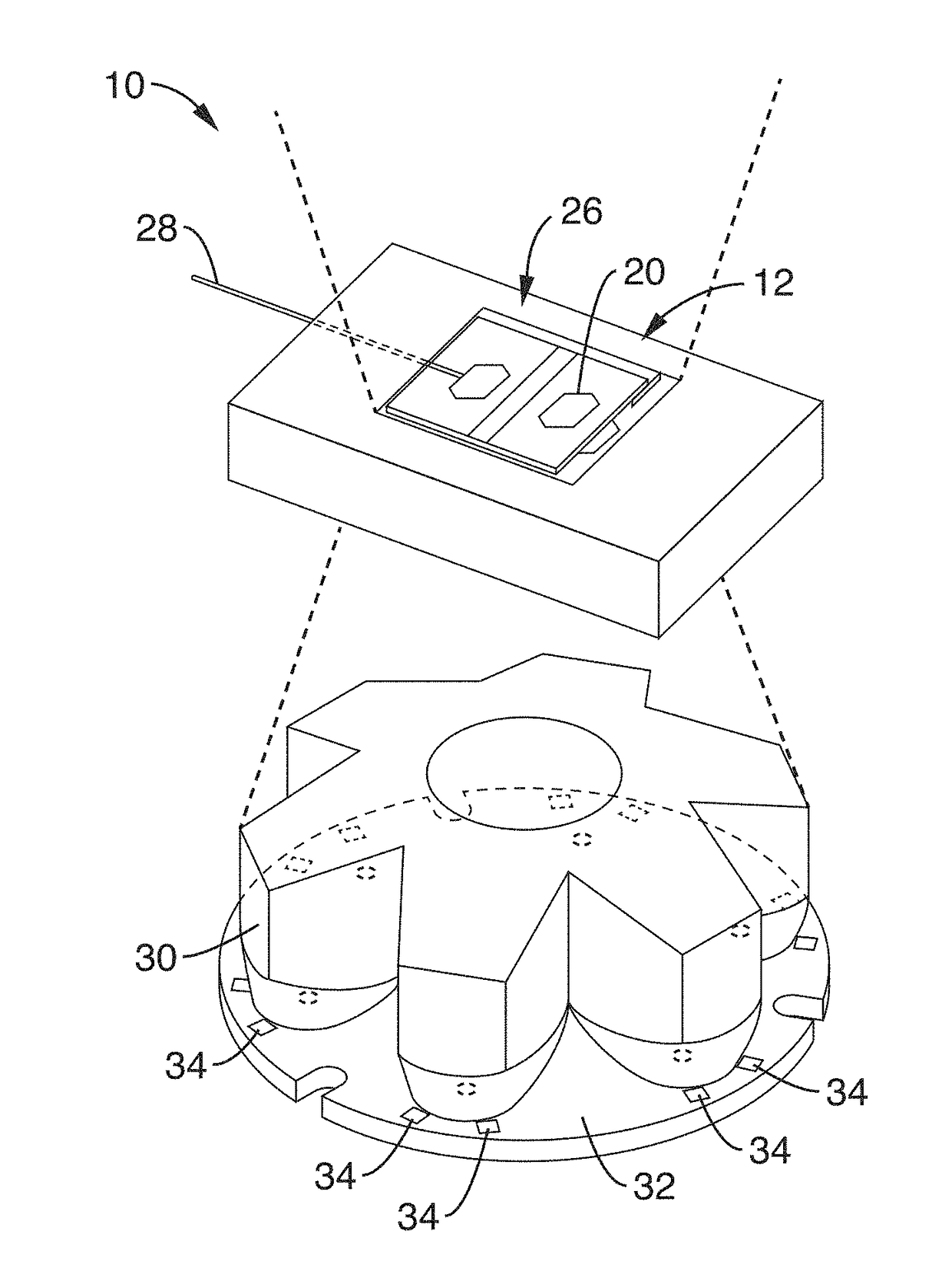
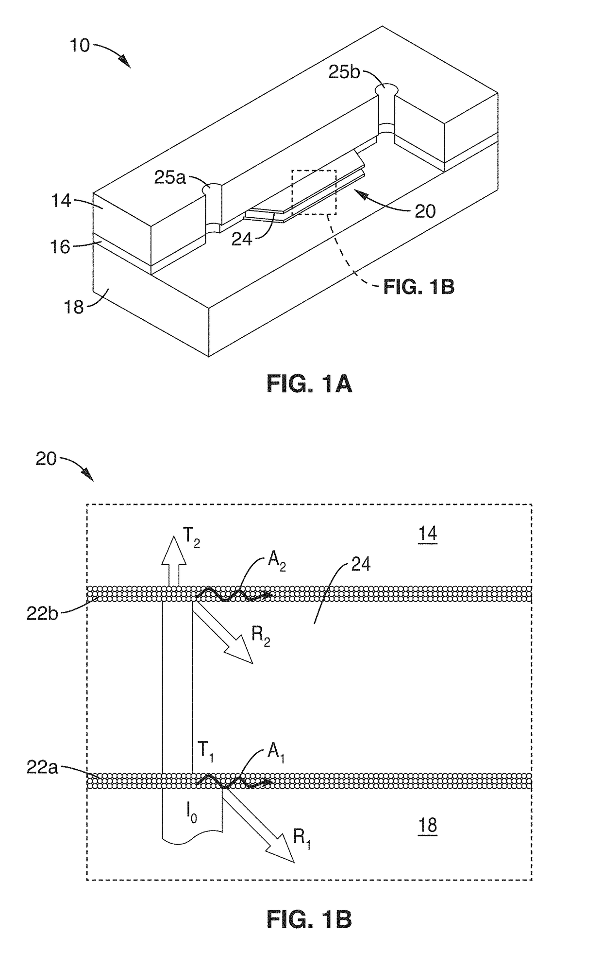
[0034]FIG. 1A shows a perspective view of an embodiment of a PCR sensing device 10 comprising an optical cavity 20 for nucleic acid amplification through polymerase chain reaction (PCR) with top and cavity layers partially removed for clarity. FIG. 1B is a schematic side view of the optical cavity 20, showing light absorpt...


PUM

PropertyMeasurementUnit
Fractionaaaaaaaaaa
Fractionaaaaaaaaaa
Fractionaaaaaaaaaa

Abstract

An LED-driven optical cavity PCR system and method is disclosed for fast, accurate and reliable PCR based diagnostics. An optical cavity comprising two thin light absorbing metal (AU) films is used for uniform light absorption and subsequent photo thermal light-to-heat conversion is employed for PCR thermal cycling.

Description

CROSS-REFERENCE TO RELATED APPLICATIONS[0001]This application is a 35 U.S.C. § 111(a) continuation of PCT international application number PCT / US2016 / 044255 filed on Jul. 27, 2016, incorporated herein by reference in its entirety, which claims priority to, and the benefit of, U.S. provisional patent application Ser. No. 62 / 199,069 filed on Jul. 30, 2015, incorporated herein by reference in its entirety. Priority is claimed to each of the foregoing applications.[0002]The above-referenced PCT international application was published as PCT International Publication No. WO 2017 / 019768 on Feb. 2, 2017, which publication is incorporated herein by reference in its entirety.STATEMENT REGARDING FEDERALLY SPONSORED RESEARCH OR DEVELOPMENT[0003]Not ApplicableINCORPORATION-BY-REFERENCE OF COMPUTER PROGRAM APPENDIX[0004]Not ApplicableNOTICE OF MATERIAL SUBJECT TO COPYRIGHT PROTECTION[0005]A portion of the material in this patent document is subject to copyright protection under the copyright law...

Claims


Application Information

Patent Timeline
IPC IPC(8): B01L7/00B01L3/00C12Q1/686
CPCB01L7/52B01L3/502707C12Q1/686B01L2300/0893B01L2300/1861B01L2300/1827
Inventor LEE, LUKE P.SON, JUN HO
Owner RGT UNIV OF CALIFORNIA
Why Eureka
Try Eureka