
Linear Solid-State Lighting With A Pulse Amplitude Control Scheme

Active Publication Date: 2018-08-23
ALEDDRA INC
View PDF4 Cites 4 Cited by
  • Summary
  • Abstract
  • Description
  • Claims
  • Application Information

AI Technical Summary

Benefits of technology

The patent describes a LLT lamp that can replace a fluorescent tube or conventional LED tube lamp. The lamp includes a housing with two lamp bases, a DC voltage module, an LED driving circuit, a pulse amplitude control module, and one or more electrical conductors protruding from each lamp base. The pulse amplitude control module generates voltage pulses in each AC cycle to power up the LED arrays. The LED driving circuit includes a power sustaining device and a transformer. The power sustaining device has a resistive load and a first control mechanism, a second control mechanism, and a third control mechanism. The first control mechanism disables both the second and third control mechanisms when an electric shock occurs. The second control mechanism disables the first control mechanism when an electric shock does not occur. The third control mechanism disables the second control mechanism when an electric shock occurs. The power sustaining device has a first DC voltage and a second DC voltage that can operate the PFC and control device. The pulse amplitude control module controls the LED voltage and current to power up the LED arrays. The technical effects of the patent include improved power conversion, reduced power consumption, and improved safety.

Problems solved by technology

But the fact is that total cost of ownership for this approach is high regardless of very low initial cost.
If the existing ballast is not compatible with the ballast-compatible LLT lamp, the consumers will have to replace the ballast.
Some facilities built long time ago incorporate different types of fixtures, which requires extensive labor for both identifying ballasts and replacing incompatible ones.
Maintenance will be complicated, sometimes for lamps and sometimes for ballasts.
The labor costs and long-term maintenance costs will be unacceptable to end users.
In this sense, any energy saved while using the ballast-compatible LLT lamps becomes meaningless with the constant energy use by the ballast.
In the long run, ballast-compatible LLT lamps are more expensive and less efficient than self-sustaining AC mains-operable LLT lamps.
All of such LLT lamps, no matter whether AC mains-operable or ballast-compatible, are electrically wired as double-ended and have one construction issue related to product safety and needed to be resolved prior to wide field deployment.
This kind of LLT lamps, if no shock prevention scheme is adopted in, always fails a safety test, which measures a through-lamp electric shock current.
Because an AC-mains voltage applies to both opposite ends of the LLT lamps, the measurement of current leakage from one end to the other consistently results in a substantial current flow, which may present a risk of an electric shock during re-lamping.
Although the LLT lamps used with a ballast can pass the current leakage test, some kinds of electric shock hazards do exist.
Experimental results show that the skin of the person who touches an exposed bi-pin may be burned due to such an electric shock.
However, a conventional shock prevention switch has an inherent issue related to an electric arc when operated with a ballast.
The feature that originally supports a fluorescent tube to function properly becomes extremely detrimental to the conventional shock prevention switch due to the electric arc likely occurring between two electrical contacts that have a high electrical potential difference with a high frequency, such as 600 V / 50 kHz.
The arcing even in a short period such as several seconds can generate high heat, burning and melting electrical contacts and neighboring plastic enclosures, creating a fire hazard.
However when used with the ballast, the electrical contacts used in the conventional shock prevention switch can easily be burned out due to the high-voltage and high-frequency arcing introduced between each gap of each pair of the electrical contacts in the conventional shock prevention switch when someone tries to abusively tweak to remove the tube lamp from the fixture with the ballast that has a power on it.
Although such a situation is rare, an internal arcing, if occurred, does cause burning and even welding of the electrical contacts and melting of the plastic enclosure, so called internal fire, creating consumer safety issues.
Not like LLT lamps with an external driver that is inherently electric-shock free if the driver can pass a dielectric withstand test used in the industry, LLT lamps with an internal driver could have a shock hazard during relamping or maintenance, when the substantial through-lamp electric shock current flows from any one of AC voltage inputs through the internal driver connecting to LED arrays to the earth ground.
Any products with electric shock or fire hazards and risk of injuries or deaths are absolutely not acceptable for consumers.
However, commercially available LLT lamps with internal drivers, single-ended or double-ended, fail to provide effective solutions to the problems of possible electric shock and internal arcing and fire.
However, a length control of the LLT lamp becomes critical to operate the LLT lamp because sometimes the double shock protection switches may not be actuated by the mechanical actuation mechanisms.
Also, the double shock protection switches directly control AC voltages such as 120 or 277 V / 50-60 Hz from the AC mains or 600 V / 45-65 kHz from the ballasts, which makes the conventional LLT lamp so vulnerable because such high voltages working on the double shock protection switches may easily cause internal fire if consumers abusively tweak the mechanical actuation mechanisms at both ends of the LLT lamp operable with a ballast during relamping.
As mentioned above, when the electric shock occurs, the first DC voltage is built up in the power sustaining device but not high enough to operate the PFC and control device.
As mentioned above, when the electric shock occurs, the power sustaining device builds up the first DC voltage, which is not high enough to operate the PFC and control device with the LED driving circuit disabled.

Method used


Image

  • Linear Solid-State Lighting With A Pulse Amplitude Control Scheme
  • Linear Solid-State Lighting With A Pulse Amplitude Control Scheme
  • Linear Solid-State Lighting With A Pulse Amplitude Control Scheme

Examples


Embodiment Construction

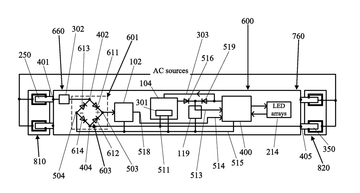
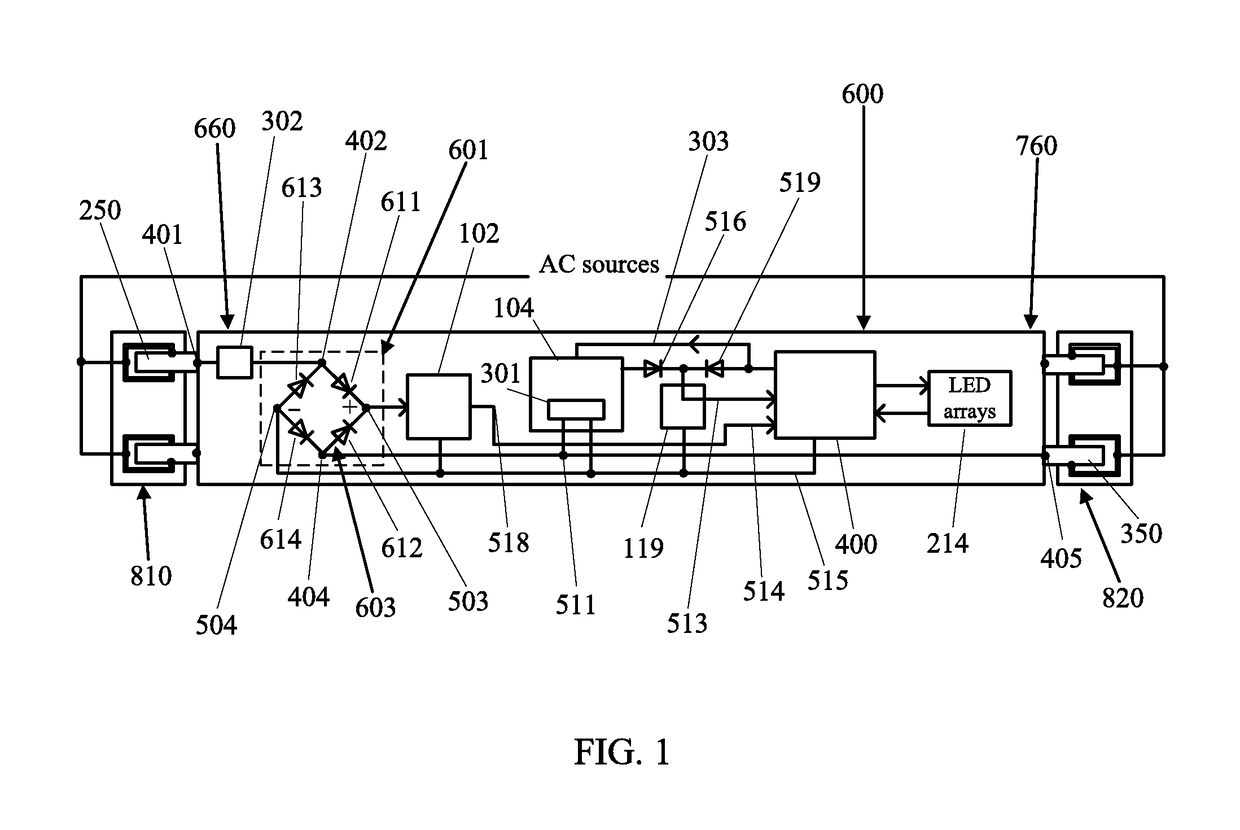
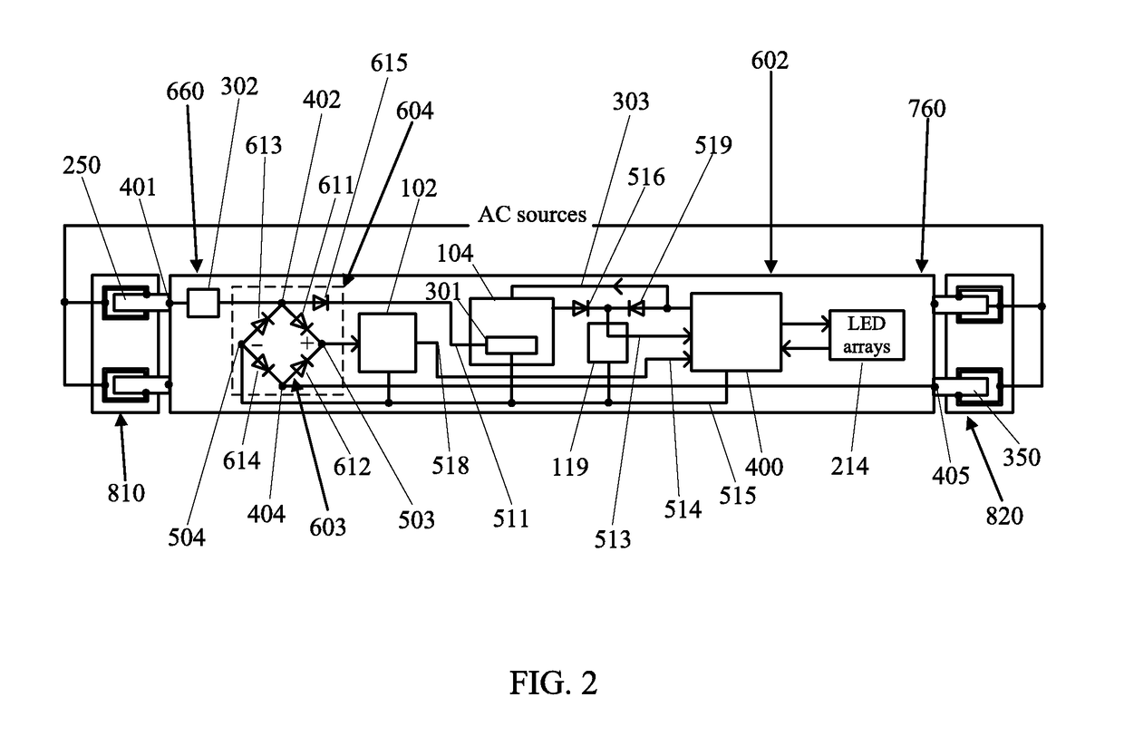
[0022]FIG. 1 is one embodiment of an LLT lamp installed in lamp fixture sockets connected with AC sources according to the present disclosure. The LLT lamp 600 comprises a housing having two ends; two lamp bases 660 and 760 each having at least one electrical conductor 250 and 350 at each end of the housing, a first input filter 302, a DC voltage module 601, a pulse amplitude control module 104, an LED driving circuit 110 (in FIG. 3), and one or more LED arrays 214. The DC voltage module 601 comprises a full-wave rectifier 603 comprising diodes 611, 612, 613, and 614 interconnected at ports 402, 404, 503, and 504. The full-wave rectifier 603 is connected to an input AC line voltage via the at least one electrical conductor 250 and 350 in each lamp base, configured to convert the input AC line voltage not only to a full-wave DC voltage but also to a half-wave DC voltage. The LED driving circuit 110 (in FIG. 3) comprises a second input filter 102 connected to the port 503 of the full-...


PUM


Abstract

A linear light-emitting diode (LED)-based tube (LLT) lamp comprises a pulse amplitude control module, a power sustaining device, an LED driving circuit, and LED arrays. The pulse amplitude control module is configured to generate one or more voltage pulses in each alternate-current (AC) cycle in response to a half-wave direct-current (DC) voltage when the LLT lamp starts to receive power from an input AC line voltage and when the half-wave DC voltage drops to a few tens of volts in each AC cycle. The power sustaining device receives the one or more voltage pulses and builds up a DC voltage depending on pulse amplitudes. When an electric shock occurs, the DC voltage built up is not high enough to operate the LED driving circuit and thus to disable the LED arrays, without electric shock current leaking into an electrical conductor of the LLT lamp during relamping or maintenance.

Description

CROSS-REFERENCE TO RELATED APPLICATIONS[0001]The present disclosure is part of a continuation-in-part (CIP) application of U.S. patent application Ser. No. 15 / 836,170, filed 8 Dec. 2017, which is a CIP application of U.S. patent application of Ser. No. 15 / 649,392 filed 13 Jul. 2017, which is a CIP application of U.S. patent application Ser. No. 15 / 444,536, filed 28 Feb. 2017 and issued as U.S. Pat. No. 9,826,595 on 21 Nov. 2017, which is a CIP application of U.S. patent application Ser. No. 15 / 362,772, filed 28 Nov. 2016, which is a CIP application of U.S. patent application Ser. No. 15 / 225,748, filed 1 Aug. 2016 and issued as U.S. Pat. No. 9,743,484 on 22 Aug. 2017, which is a CIP application of U.S. patent application Ser. No. 14 / 818,041, filed 4 Aug. 2015 and issued as U.S. Pat. No. 9,420,663 on 16 Aug. 2016, which is a CIP application of U.S. patent application Ser. No. 14 / 688,841, filed 16 Apr. 2015 and issued as U.S. Pat. No. 9,288,867 on 15 Mar. 2016, which is a CIP applicati...

Claims


Application Information

Patent Timeline
IPC IPC(8): F21V25/04H05B33/08H02M1/32H02M7/217F21K9/272H05B44/00
CPCF21V25/04H05B33/0815H02M1/32H02M7/217H05B33/0884F21K9/272F21Y2103/10F21Y2115/10H05B45/355H05B45/3578H05B45/375H05B47/26
Inventor HSIA, CHUNGHO
Owner ALEDDRA INC
Features
  • Generate Ideas
  • Intellectual Property
  • Life Sciences
  • Materials
  • Tech Scout
  • Unparalleled Data Quality
  • Higher Quality Content
  • 60% Fewer Hallucinations
Learn More