Brain activity measurement and feedback system

a technology of brain activity and feedback system, which is applied in the field of headmounted devices, can solve the problems of not being able to adapt to diagnosis or treatment, presenting a risk to the patent, and being difficult to wear, and achieves the effect of convenient and comfortable wear and simple us

Inactive Publication Date: 2018-08-23
MINDMAZE HLDG SA
View PDF1 Cites 88 Cited by
  • Summary
  • Abstract
  • Description
  • Claims
  • Application Information

AI Technical Summary

Benefits of technology

[0018]It is an aim of the invention to provide a brain activity measurement and feedback system that is convenient and comfortable to wear, reliable, and simple to use.
[0019]It would be advantages to provide a system that is easily washable and sterilizable.
[0020]It would be advantageous to provide a system that saves time for placement and operation.

Problems solved by technology

A disadvantage of such devices is that they can be complicated and expensive.
Also, conventional systems are based on tracking actual movements and are therefore not adapted for diagnosis or treatment in the very early stages after an occurrence of stroke where movement is impaired or very limited.
They may also present a risk to the patent if, for example, the body part is moved too quickly or if part of the heavy actuation equipment falls on the patent.
They are also not particularly portable, which generally prohibits home use and use in a hospital environment, and can also be difficult to adapt to the rehabilitation requirements of a particular patient since the range of permitted movements is often confined by a mechanical system.
A drawback of certain VR based systems is that they only measure the response of the body part to an instructed task.
This may lead to areas of the brain being treated other than those which are damaged, or at least an inability to directly monitors a particular area of the brain.
Moreover, the patient is not fully immersed in the VR environment since they look to a separate monitor screen to view the VR environment.
In WO 2011 / 123059 and US 2013 / 046206, VR based systems with brain monitoring and motion tracking are described, the main drawback of known systems being that they do not reliably nor accurately control synchronization between stimulation or action signals and brain activity signals, which may lead to incorrect or inaccurate processing and read out of brain response signals as a function of stimuli or actions.
In particular, there is no comprehensive system that comprises stereoscopic display of virtual and / or augmented reality information, where some content may be related to some extent to the physiological / behavioral activity of any related user and registered by the system, and / or any information coming from the environment.
Current solutions compromise the synchronization quality, especially in the amount of jitter between the measured neural signal (e.g., EEG) and the simulation signal (e.g., display of a cue).
Due to this, not only the signal to noise ratio of acquired signals is lowered but also limit the analysis to lower frequencies (typically less than 30 Hz).
The cost of devices is of course also an important issue in consumer applications.
In medical applications the cost of diagnosis or treatment is important, whereby such costs are affected not only by the cost of devices used per se, but also the cost of using the devices, including: ease of set up, manipulation and of obtaining and interpreting results; reuse and sterilization.
The positioning of the cap, connection of electrodes and the chip strap or other fixing devices render such conventional systems uninteresting for many consumer applications and tedious even for medical applications.
Drawbacks include: not visually aesthetic; overheating of the electrode contact due to reduced air-flow; time-consuming placement of the cap because of adjustments to anatomical inion-nasion distance to ensure 10-20 system and complex set-up (e.g., placement of electrodes, contacts, connectivity etc.); the need for separate electronics and cap electrodes to allow washing of the electrodes.
All three of these prior systems suffer from many of the drawbacks mentioned above.
Further EEG head-mounted devices are disclosed in US 2015 / 0011857, US 2013 / 0172721, WO 2013 / 124366, US2011 / 0282231, and US2013 / 0303874, however that also suffer at least some of the drawbacks including the difficulty to adjust for different head sizes, non-optimal placement of electrodes, difficulty to allow washing of the electrodes / head set for re-use, discomfort to wear and / or high manufacturing costs.

Method used


Image

  • Brain activity measurement and feedback system
  • Brain activity measurement and feedback system
  • Brain activity measurement and feedback system

Examples


example 2

ain-Computer Interface with Virtual Reality Feedback with Head-Mounted Display, Robotic System and Functional Electrical Stimulation

[0197]Objective:

[0198]To provide optimal training for patients with upper movements movement deficits resulting from neurological problems (e.g., ALS, stroke, brain injury, locked-in syndrome, Parkinson disease etc.). These patients would require training to reintegrate the lost / degraded movement function. A system that reads their intention to make a functional movement and provide an assistance in completing the movement could enhance the rehabilitation outcome.

[0199]For this purpose, the system could exploit Hebbian learning in associating brain's input and output areas in reintegrating the lost movement function. The Hebbian principle is “Any two systems of cells in the brain that are repeatedly active at the same time will tend to become ‘associated’, so that activity in one facilitates activity in the other.”

[0200]In the present example, the two s...

example 3

puter Interface and Motion Data Activated Neural Stimulation with Augmented Reality Feedback

[0237]Objective

[0238]A system could provide precise neural stimulation in relation to the actions performed by a patient in real world, resulting in reinforcement of neural patterns for intended behaviors.

[0239]Description

[0240]Actions of the user and that of a second person and objects in the scene are captured with a camera system for behavioral analysis. Additionally neural data is recorded with one of of the modalities (EEG, ECOG etc.) are synchronized with IMU data. The video captured from the camera system is interleaved with virtual objects to generate 3D augmented reality feedback and provided to the user though head-mounted display. Finally, appropriate neural stimulation parameters are generated in the control system and sent to the neural stimulation.

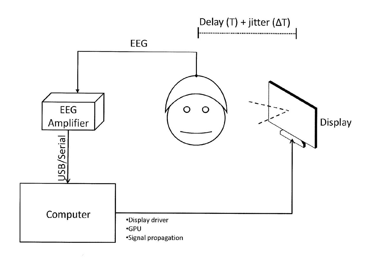
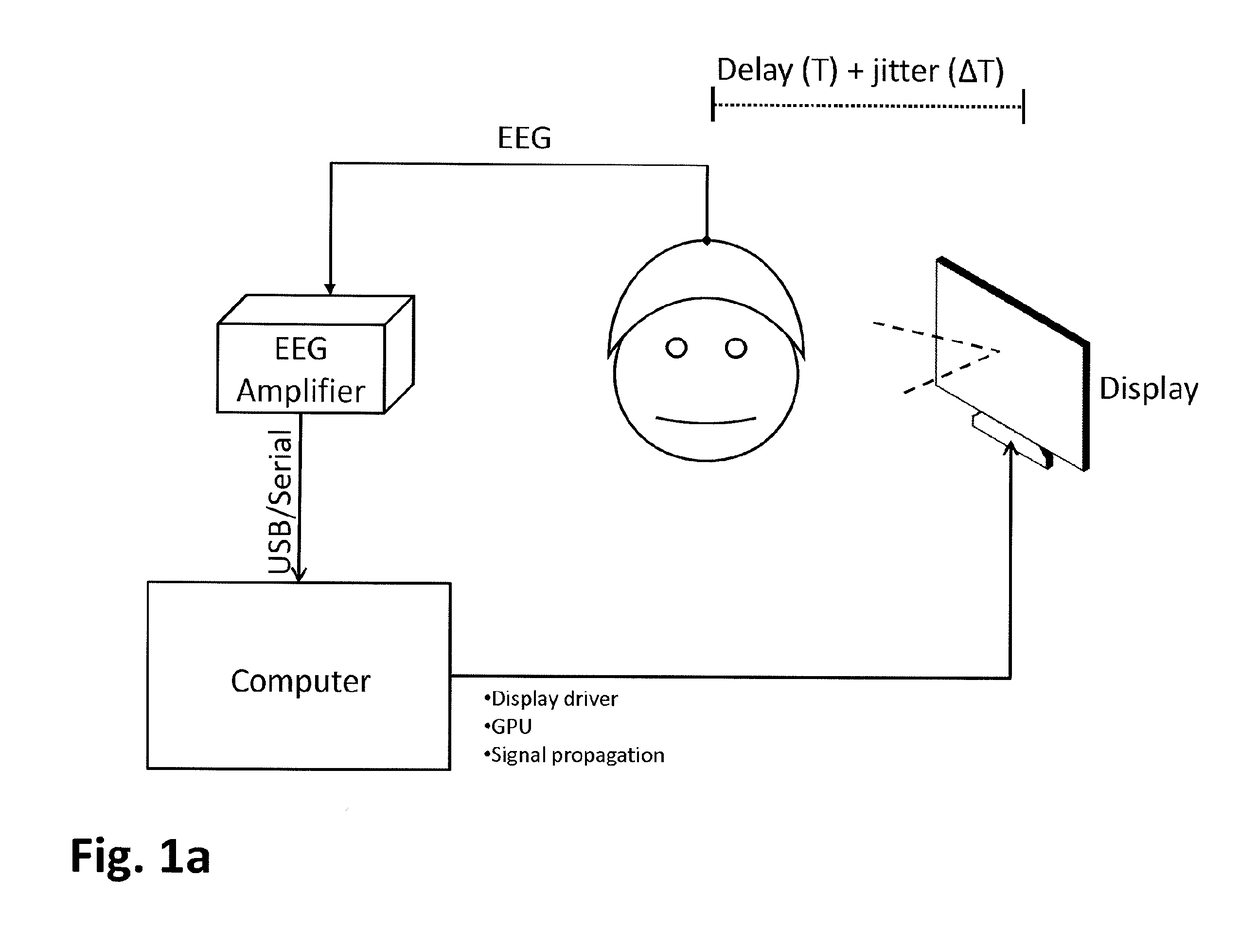
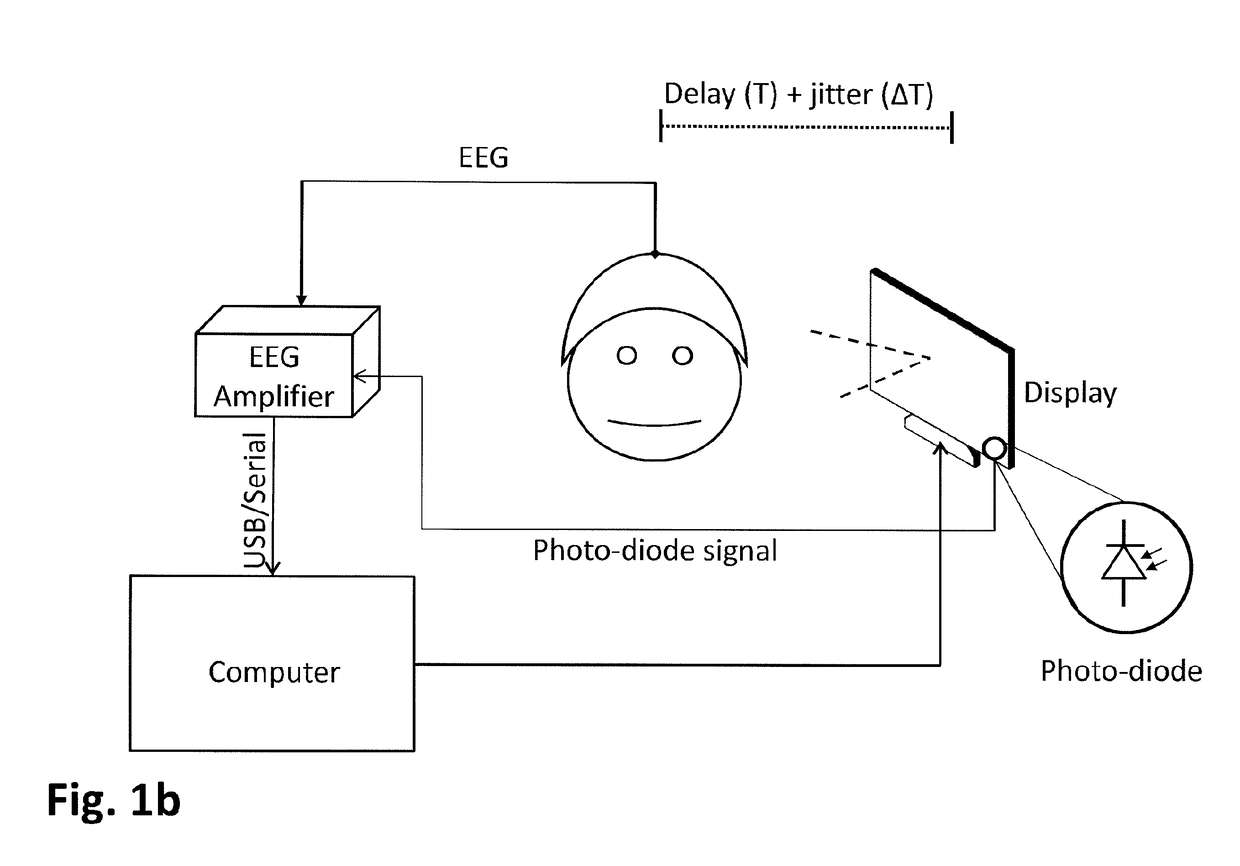
[0241]For delay and jitter between user's behavioral and physiological measures and neural stimulation should be optimized for effect...


PUM


Abstract

A head set (2) comprises a brain electrical activity (EEG) sensing device (3) comprising EEG sensors (22) configured to be mounted on a head of a wearer so as to position the EEG sensors (22) at selected positions of interest over the wearers scalp, the EEG sensing device comprising a sensor support (4) and a flexible circuit (6) assembled to the sensor support. The sensor support and flexible circuit comprise a central stem (4a, 6a) configured to extend along a center plane of the top of the head in a direction from a nose to a centre of the back of a wearers head, a front lateral branch (4b, 6b) configured to extend across a front portion of a wearer's head extending laterally from the central stem, a center lateral branch (4c, 6c) configured to extend across a top portion of a wearer's head essentially between the wearer's ears, and a rear lateral branch (4d, 6d) configured to extend across a back portion of a wearer's head. The sensor support (4) comprises a base wall (401) and side walls (402) extending along edges of the base wall to form an essentially flat “U” shaped channel (403) in which the flexible circuit (6) is inserted and the base wall comprise EEG sensor orifices (404) to allow access to the EEG sensor contacts or electrodes on the flexible circuit.

Description

TECHNICAL FIELD[0001]The present invention relates to a head-mounted device to measure or monitor cortical activity of a user, and optionally to generate stimuli and / or to provide feedback to the user. Applications for use of the invention may include gaming, training, learning of sensory-motor skills, diagnosis or treatment of neurological injury or disease.DESCRIPTION OF RELATED ART[0002]Neurological injury which follows a stroke often manifests as hemiparesis or other partial paralysis of the body. Current rehabilitation procedures are often based on exercises performed by the impaired body part, the movement of which is tracked in real-time to provide feedback to the patient and / or a medical practitioner. Computer controlled mechanical actuation systems have been used to track a position of, and force applied by, a body part such an arm of a patient as a predetermined movement pattern is executed by the patient. To reduce patient fatigue such systems can support the patient, for...

Claims


Application Information

Patent Timeline
Patent Type & Authority Applications(United States)
IPC IPC(8): G06F3/01A61B5/0478A61B5/00A61B5/0482A61B5/375
CPCG06F3/015G06F3/013A61B5/0478A61B5/6814A61B5/0482A61B5/01A61B5/0488A61B5/744A61B5/1128A61B5/1114A61B5/0533G06F3/012G02B27/0172H01L31/0232A61B5/7285A61B5/7445A61B5/743A61B5/4836A61B5/486A61B5/6831A61B2562/164A61B2562/166A61B5/0036A61B5/30A61B5/318A61B5/375A61B5/398A61B5/291A61B5/389H01L33/58G02B27/017
Inventor TADI, TEJGARIPELLI, GANGADHARPEREZ MARCOS, DANIELBOURDAUD, NICOLASCHAVEZ CASTANEDA, GERARDO DE JESUSBOLOMEY, LEANDRE
Owner MINDMAZE HLDG SA
Why Eureka
Try Eureka