Color image display device and color image display method

a display device and color image technology, applied in static indicating devices, non-linear optics, instruments, etc., can solve the problems of low light-use efficiency and maximum luminance of the liquid crystal display device using color filters, low light-use efficiency and low light-use efficiency when compared to the simple rgb subframe system, and decrease in the range of color reproduction. , to achieve the effect of increasing the transparent display area of the image to be displayed, reducing display color saturation, and inhibi

Inactive Publication Date: 2018-08-23
SHARP KK
View PDF6 Cites 7 Cited by
  • Summary
  • Abstract
  • Description
  • Claims
  • Application Information

AI Technical Summary

Benefits of technology

[0068]According to the first aspect of the present invention, the drive light source data, which designates the color and the intensity of light emitted by the light source portion during each of the subframe periods in each frame period, is generated by modifying the initial light source data on the basis of the input data representing the image to be displayed, such that the transparency of the transparent display area in the image to be displayed increases. Thus, it is possible to inhibit color breakup and a reduction in display color saturation while enhancing the transparency of the transparent display area.
[0069]According to the second aspect of the present invention, the transparent display area proportion, which represents a proportion of the transparent display area in the image to be displayed, is obtained on the basis of the input data, and the drive light source data is generated by modifying the initial light source data in accordance with the transparent display area proportion such that the transparency of the transparent display area increases. Thus, it is possible to inhibit color breakup and a reduction in display color saturation while enhancing the transparency of the transparent display area in accordance with the transparent display area proportion.
[0070]According to the third aspect of the present invention, the target color display area proportion is obtained on the basis of the input data, for each of the target colors determined for their respective subframe periods in each frame period, such that the target color for a subframe period corresponding to a color whose saturation is minimum or maximum among all colors of light respectively designated by the initial light source data for the subframe periods, is a transparent color and the target colors for the other subframe periods are colors of light respectively designated by the initial light source data for those other subframe periods. Then, the drive light source data is generated by modifying the initial light source data such that the light emitted by the light source portion during each subframe period approximates to the light in the target color in accordance with the target color display area proportion. Thus, it is possible to inhibit color breakup and a reduction in chromatic color saturation in a display image while enhancing the transparency of the transparent display area.
[0071]According to the fourth aspect of the present invention, the first, second, and third light sources, which respectively emit light in the three primary colors consisting of the first, second, and third primary colors, are used, and the light source data that is used as the initial light source data causes the first, second, and third light sources to emit light during the first subframe period, causes only the first light source to emit light during the second subframe period, causes only the second light source to emit light during the third subframe period, and causes only the third light source to emit light during the fourth subframe period, whereby effects similar to those achieved by the third aspect of the present invention can be achieved.
[0072]According to the fifth aspect of the present invention, the drive light source data is generated by modifying the initial light source data such that the emission intensities of the first, second, and third light sources during the first subframe period increase in accordance with the transparent display area proportion based on the input data. As a result, the average intensity of the light emitted by each light source to form the image to be displayed, taken from among a plurality of subframe periods corresponding to one frame period, becomes higher than the average emission intensity of the light source among the subframe periods, which is indicated by the initial light source data. Thus, in the case of a field-sequential color image display device with a display portion configured such that the transparency of the transparent display area increases with the emission intensity of the light source portion, as in the case of a housing-case-type transparent display, it is possible to achieve effects similar to those achieved by the fourth aspect of the present invention.
[0073]According to the sixth aspect of the present invention, the drive light source data is generated by modifying the initial light source data such that the emission intensities of the first, second, and third light sources during the first subframe period decrease in accordance with the transparent display area proportion based on the input data. As a result, the average intensity of the light emitted by each light source to form the image to be displayed, taken from among a plurality of subframe periods corresponding to one frame period, becomes lower than the average emission intensity of the light source among the subframe periods, which is indicated by the initial light source data. Thus, in the case of a field-sequential color image display device with a display portion configured such that the transparency of the transparent display area increases as the emission intensity of the light source portion decreases, as in the case of a stand-alone-type transparent display, it is possible to achieve effects similar to those achieved by the fourth aspect of the present invention.

Problems solved by technology

However, about ⅔ of the backlight that illuminates a liquid crystal panel is absorbed by the color filters, and therefore such a liquid crystal display device using color filters has low light-use efficiency.
Accordingly, in the case where the common color subframe system is employed for the field-sequential liquid crystal display device, light-use efficiency and maximum luminance are low when compared to the simple RGB subframe system.
However, these approaches involve either a decrease in the range of color reproduction due to reduced color saturation or both a reduction in the effect of inhibiting color breakup and deterioration of the quality of additive color mixing.
Therefore, it is not possible to achieve enhanced luminance, as achieved in the aforementioned approaches for inhibiting color breakup and enhancing light-use efficiency or maximum luminance.
Therefore, when an image is displayed in two or more colors, color breakup inhibition and luminance enhancement cannot be achieved properly.
The stand-alone-type transparent display has difficulty in becoming completely transparent when the front light is lit up.

Method used


Image

  • Color image display device and color image display method
  • Color image display device and color image display method
  • Color image display device and color image display method

Examples


first embodiment

1. First Embodiment

[0102]

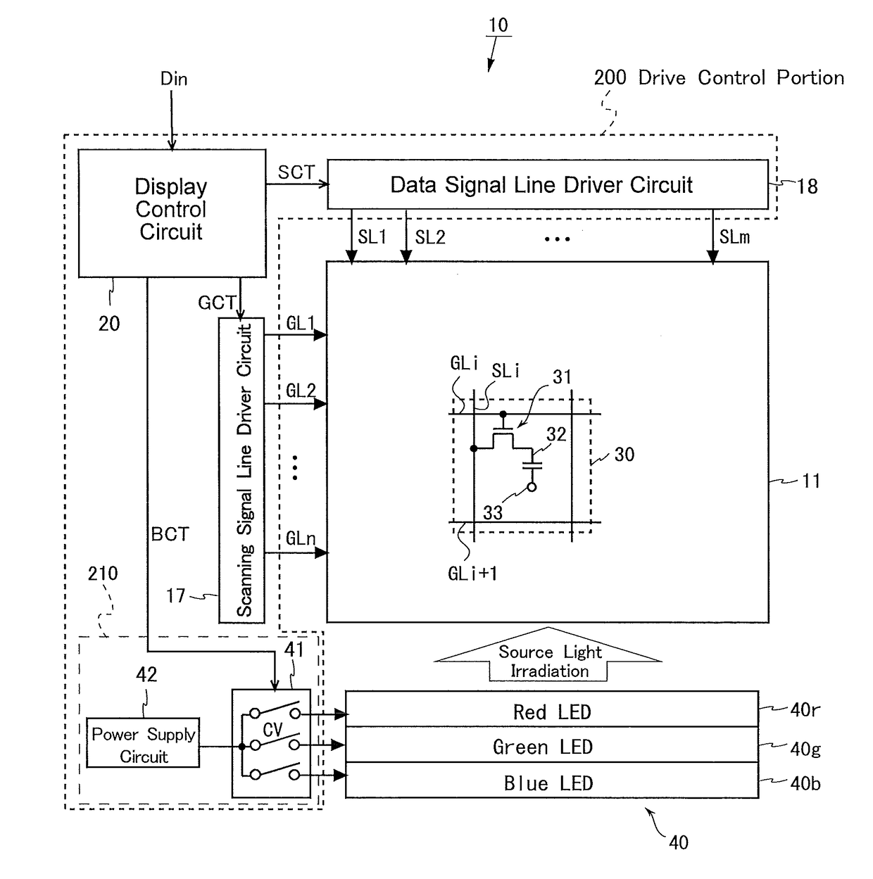
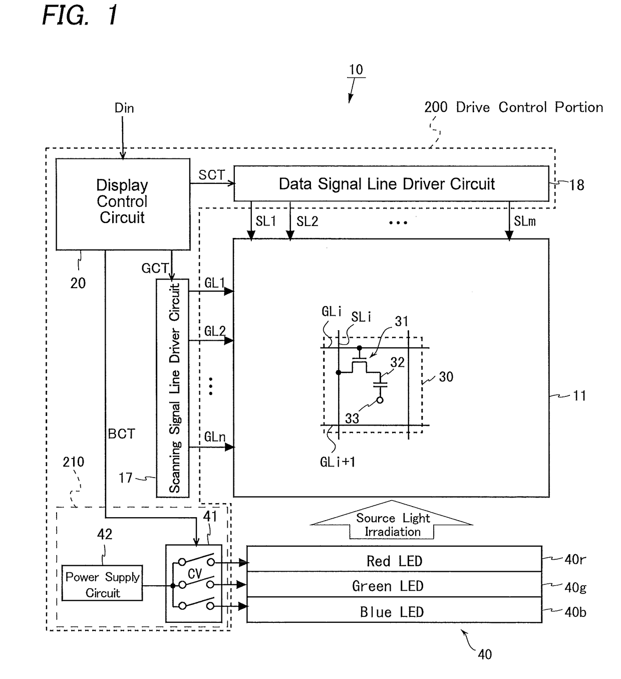
[0103]FIG. 1 is a schematic block diagram illustrating a general configuration of a field-sequential liquid crystal display device according to a first embodiment of the present invention. The liquid crystal display device 10 displays a color image by a field-sequential system in which one frame period is divided into three or four subframe periods (also referred to as “field periods”). The liquid crystal display device 10 includes a liquid crystal panel 11, which serves as a display panel, a display control circuit 20, a scanning signal line driver circuit 17, a data signal line driver circuit 18, a light source unit 40, and a light source driver portion 210 including a switch group 41 and a power supply circuit 42. Note that the display control circuit 20, the scanning signal line driver circuit 17, the data signal line driver circuit 18, and the light source driver portion 210 (i.e., the switch group 41 and the power supply circuit 222) constitute a drive...

second embodiment

2. Second Embodiment

[0232]Next, a field-sequential liquid crystal display device according to a second embodiment of the present invention will be described. The present embodiment differs from the first embodiment in the target color determination processing by the input data judgment portion in the control drive portion, but the other features are the same as in the first embodiment. Accordingly, in the following, elements of the present embodiment that are the same as or correspond to the elements of the first embodiment are denoted by the same reference characters and any detailed descriptions thereof will be omitted.

[0233]

[0234]In the present embodiment, the input data judgment portion 202 determines a target color TCk (where k=1 to L) as below. The present embodiment and the first embodiment are the same in that as a target color candidate TCC=(Rt, Gt, BL), a transparent color that satisfies formulas (8) to (11) is provided in the case of the housing-case-type transparent disp...


PUM


Abstract

The present invention provides a field-sequential color image display device inhibiting color breakup and a reduction of the range of color reproduction while achieving enhanced transparency of a transparent display area.
In the field-sequential liquid crystal display device, a light source data computation portion (206) obtains drive light source data Ek by modifying initial light source data on the basis of a transparent color, which is a target color TCk, and a target color display area proportion TPk, which is obtained from input data Din, such that transparency of a transparent display area in an image to be displayed increases. On the basis of the drive light source data Ek, a light source driver portion (210) drives red, green, and blue LEDs of a light source portion (120) for respective frame periods within a frame period during which the image represented by the input data is to be displayed. A spatial light modulation drive portion (214) controls transmittance through a liquid crystal panel in a pixel array portion (110), for each pixel so as to maximize transmittance through the transparent display area.

Description

TECHNICAL FIELD[0001]The present invention relates to color image display devices, more specifically to a color image display device, such as a liquid crystal display device which is capable of displaying a color image by a field-sequential system while achieving display in a transparent display mode.BACKGROUND ART[0002]Most liquid crystal display devices that display color images include color filters respectively transmitting red (R), green (G), and blue (B) light therethrough, the filters being provided for each set of three subpixels into which each pixel is divided. However, about ⅔ of the backlight that illuminates a liquid crystal panel is absorbed by the color filters, and therefore such a liquid crystal display device using color filters has low light-use efficiency. Accordingly, field-sequential liquid crystal display devices, which achieve display in colors without using color filters, are drawing attention.[0003]In a typical field-sequential liquid crystal display device...

Claims


Application Information

Patent Timeline
Patent Type & Authority Applications(United States)
IPC IPC(8): G09G3/36G09G3/20
CPCG09G3/3607G09G3/2003G09G3/3648G09G2320/0242G09G3/3413G09G2310/0235G09G2320/0633G09G2320/064G02F1/133622
Inventor KOBAYASHI, MASAMITSU
Owner SHARP KK
Why Eureka
Try Eureka