
Passive flow control mechanism for suppressing tollmien-schlichting waves, delaying transition to turbulence and reducing drag

a flow control and tollmien-schlichting technology, applied in the direction of airflow influencers, drag reduction, influencers by generating vortices, etc., can solve the problems of increasing energy consumption, vibration and noise, and difficulty in avoiding turbulent flow, so as to reduce drag and delay the effect of transition to turbulen

Inactive Publication Date: 2018-08-30
LOMBARD
View PDF10 Cites 28 Cited by
  • Summary
  • Abstract
  • Description
  • Claims
  • Application Information

AI Technical Summary

Benefits of technology

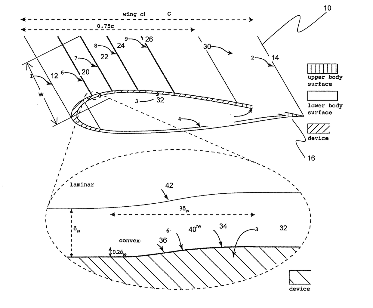
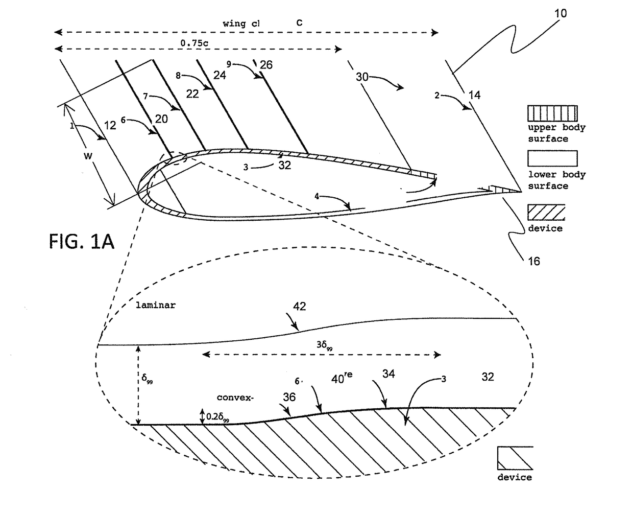
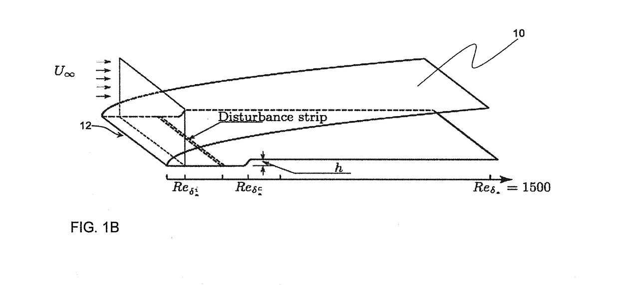
The invention is a way to control the flow of air over a surface, which reduces drag and delays the transition to turbulence. This is achieved by using smooth steps located in the boundary layer of the surface, which disrupt the smooth flow of air and help to keep it in a laminous state. The smooth steps are placed in the direction of the airflow, with one step positioned next to another to prevent pressure on nearby steps. When multiple parallel steps are used, their height should increase in the direction of the airflow. This invention is particularly useful for airplanes and other objects that need to move through the air smoothly.

Problems solved by technology

It is known that turbulent flow leads to increase energy consumption and may cause vibrations and noise.
In many situations where a solid body has to move through a viscous fluid, e. g., an airplane flying in the atmosphere, a propeller blade rotating in air, or a ship moving through water, this is undesirable.
However, it is difficult to avoid turbulent flow.
The theoretical understanding of turbulence, including the factors responsible for laminar flow turning into turbulent flow, is still very limited.
Flow control mechanisms based on blowing / sucking require maintenance of the holes and, in some cases, additional weight and power consumption, which are detrimental to the operational performance of the aircraft, due to compressors adapted to blow / suck air into the boundary.
For laminar flow control systems based on suction holes to provide laminar flow over a significant portion of the aerodynamic surface complex ducting are required as well as weighty compressors and increased energy consumption possibly detracting from the potential economic benefits.
However, these methods still require complex ducting and can be further complicated by using movable doors for controlling the amount of mass flow through the porous surfaces.
The past failures in generating Laminar Flow Control over wings have been driven by a lack of a clear economic benefit in implementing these strategies.

Method used


Image

  • Passive flow control mechanism for suppressing tollmien-schlichting waves, delaying transition to turbulence and reducing drag
  • Passive flow control mechanism for suppressing tollmien-schlichting waves, delaying transition to turbulence and reducing drag
  • Passive flow control mechanism for suppressing tollmien-schlichting waves, delaying transition to turbulence and reducing drag

Examples


Embodiment Construction

[0053]The following description is not intended to limit the scope of the invention in any way as they are exemplary in nature and serve to describe the best mode of the invention known to the inventors as of the filing date hereof. Consequently, changes may be made in the arrangement and / or function of any of the elements described in the disclosed exemplary embodiments without departing from the spirit and scope of the invention.

[0054]Those skilled in the art will appreciate that elements in the figures are illustrated for simplicity and clarity and have not necessarily been drawn to scale. For example, dimensions may be exaggerated relative to other elements to help improve understanding of the invention and its embodiments. Furthermore, when the terms ‘first’, ‘second’, and the like are used herein, their use is intended for distinguishing between similar elements and not necessarily for describing a sequential or chronological order. Moreover, relative terms like ‘front’, ‘back...


PUM


Abstract

A body adapted for relative movement with respect to a fluid, said movement creating a flow of fluid with respect to the body in a relative flow direction, said body having at least one surface with a surface profile exposed to the fluid and comprising at least one smooth step facing in relative flow direction towards the flow, said step having a height between 4% and 30% of the local boundary layer thickness (δ99) of the fluid contacting the body in the vicinity of the step.

Description

CROSS REFERENCE TO RELATED APPLICATIONS[0001]This application claims the benefit of U.S. Provisional Application 62 / 460,784, filed Feb. 18, 2017, entitled: PASSIVE FLOW CONTROL MECHANISM FOR SUPPRESSING TOLLMIENSCHLICHTING WAVES, DELAYING TRANSITION TO TURBULENCE AND REDUCING DRAG, the content of the entirety of which is explicitly incorporated herein by reference and relied upon to define features for which protection may be sought hereby as it is believed that the entirety thereof contributes to solving the technical problem underlying the invention, some features that may be mentioned hereunder being of particular importance.COPYRIGHT & LEGAL NOTICE[0002]A portion of the disclosure of this patent document contains material which is subject to copyright protection. The copyright owner has no objection to the facsimile reproduction by anyone of the patent document or the patent disclosure as it appears in the Patent and Trademark Office patent file or records, but otherwise reserve...

Claims


Application Information

Patent Timeline
Patent Type & Authority Applications(United States)
IPC IPC(8): B64C21/02B64C21/06B64C23/06B64C21/10
CPCB64C2230/06B64C21/025B64C21/06B64C23/076B64C21/10B64C2230/20B64C2230/26Y02T50/10B64C2003/148
Inventor LOMBARD
Owner LOMBARD
Learn More