Inverter device

a technology of inverter and power supply, which is applied in the direction of reactive power adjustment/elimination/compensation, power conversion system, electrical equipment, etc., can solve the problems of instantaneous power failure, instantaneous voltage rise, instantaneous voltage drop, etc., to reduce the cost reduce the size of the inverter device, and suppress the overcurrent more reliably

Active Publication Date: 2018-08-30
ORMON CORP
View PDF3 Cites 1 Cited by
  • Summary
  • Abstract
  • Description
  • Claims
  • Application Information

AI Technical Summary

Benefits of technology

[0023]According to the inverter device of the present invention, an overcurrent can be suppressed without increasing a processing load on a side supplying the pulse signal to the switching unit in accordance with the system voltage. In addition, since determination is conducted based on a current actually flowing in the output coil, instead of the system voltage, an overcurrent can be suppressed more reliably. Since an output coil having an inductance value smaller than that in the related art can be used, it is possible to realize miniaturization and cost reduction of the inverter device.

Problems solved by technology

Incidentally, in the power system P, problems such as an instantaneous voltage rise, an instantaneous voltage drop, a sudden phase change, and an instantaneous power failure may occur.

Method used


Image

  • Inverter device
  • Inverter device
  • Inverter device

Examples


first embodiment

1.1 Schematic Configuration

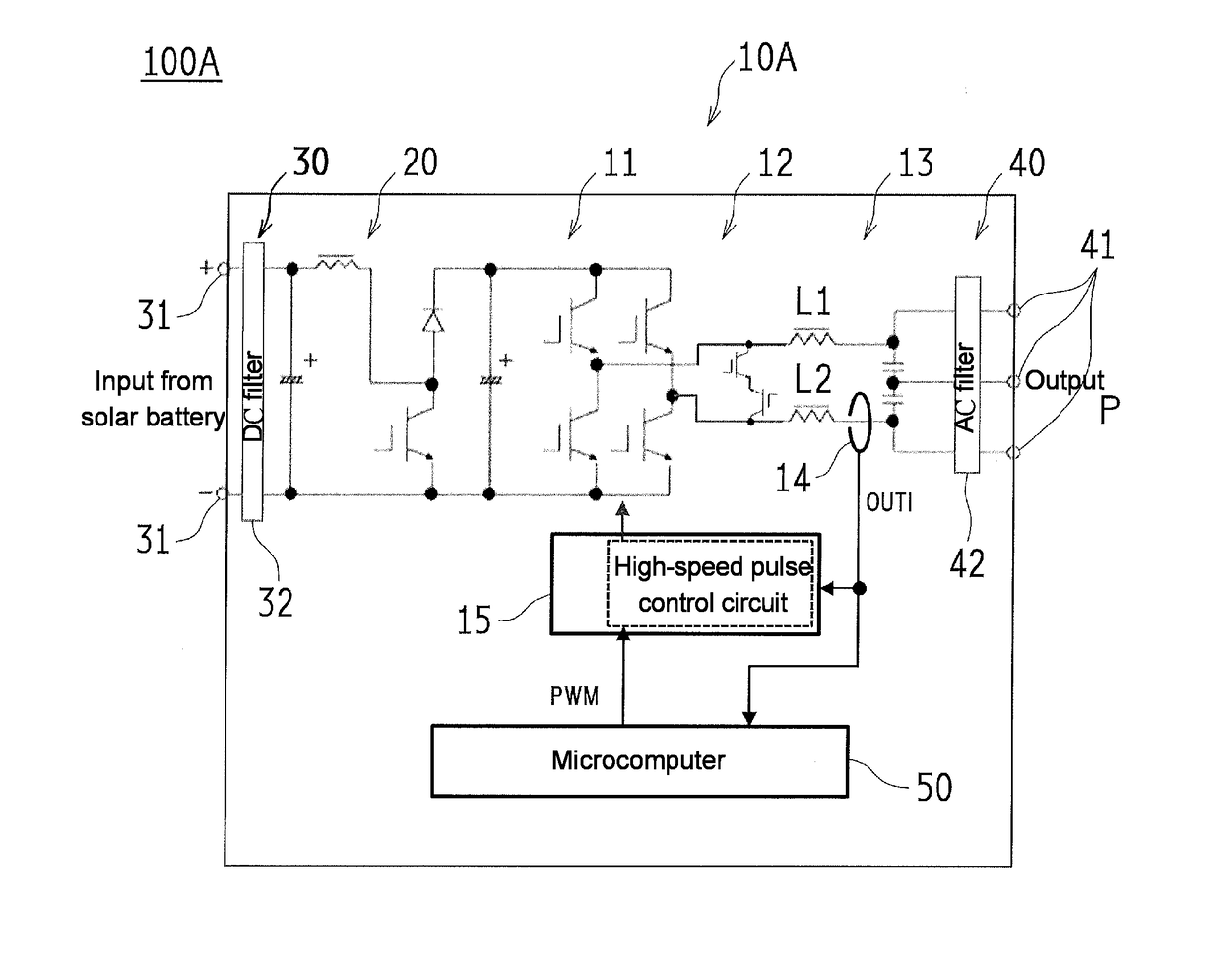
[0055]FIG. 3 is a schematic view illustrating a configuration of a power conditioner 100A including an inverter 10A according to a first embodiment of the present invention.

[0056]As illustrated in FIG. 3, the power conditioner 100A performing an interconnection output to the power system P has an input unit 30 which includes an input terminal 31 to which an output of a solar battery S or the like is connected, and a DC filter 32; a DC / DC converter 20 which boost a DC voltage input to the input unit 30; an inverter 10A which converts a DC voltage output from the DC / DC converter 20 into an AC voltage; an output unit 40 which includes an output terminal 41 for external connection and an AC filter 42 between the output terminal 41 and an output from the inverter 10A; and a microcomputer 50 controls an output of a PWM drive signal to the inverter 10A and the like.

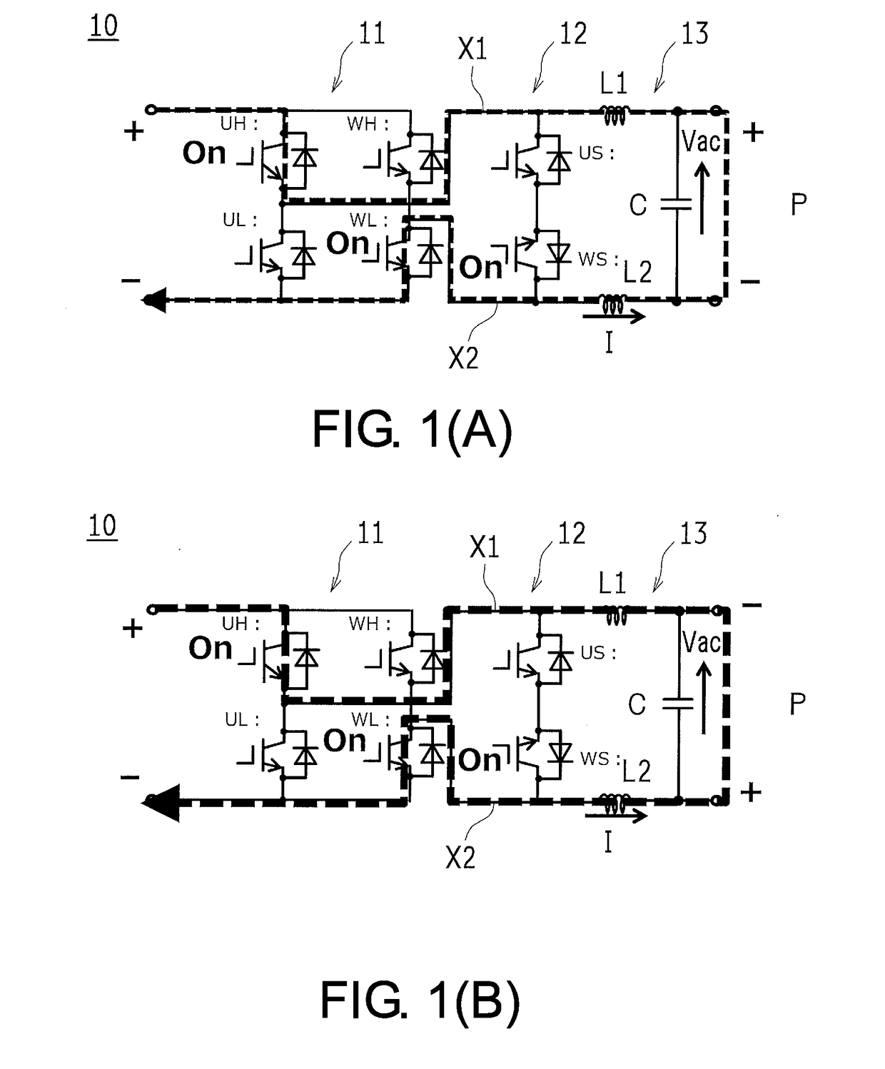
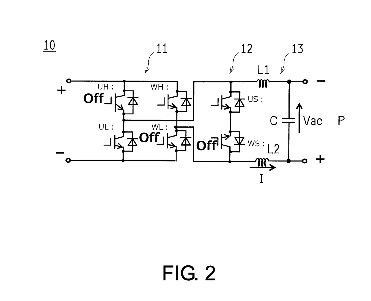
[0057]Similar to the inverter 10 described above, the inverter 10A includes the switching circuit 1...

second embodiment

2.1 Remaining Problem of First Embodiment

[0077]Although an overcurrent can be suppressed when high-speed pulse control processing by the high-speed pulse control circuit 15 of the first embodiment described above is added, a PWM drive signal output from the microcomputer 50 is controlled forcibly and separately from the microcomputer 50. Therefore, erroneous PWM control continues during a period until the microcomputer 50 recognizes that the state of the power system P has changed, and the high-speed pulse control processing may operate again in succession (chattering) as a result.

[0078]FIG. 8 is a waveform chart showing an example when the high-speed pulse control circuit 15 of the first embodiment operates high-speed pulse control processing in succession. As the conditions at this time, the output power was 4.8 kW, the input phase was 45°, the rapid change phase was +41°, and the post-phase voltage was 104 Vrms. FIG. 9 is a waveform chart showing an example when the high-speed pu...


PUM


Abstract

An inverter has a plurality of switching elements, the states of which are each switched by a pulse signal supplied in accordance with a power grid voltage. The inverter is provided with: a switching circuit that converts an input DC voltage to an AC voltage and outputs the AC voltage to a pair of output lines; a filter circuit having output coils inserted in the output lines; a current detection sensor that detects the current flowing through the output coils; and a high-speed pulse control circuit that, when an absolute value of the detected current is a threshold value or more, stops the supply of the pulse signal to the switching circuit.

Description

TECHNICAL FIELD[0001]The present invention relates to an inverter device which performs an interconnection output to a power system and particularly relates to an inverter device which is provided with countermeasures for protection from an overcurrent caused due to a sudden phase change or the like on the power system side.BACKGROUND ART[0002]FIG. 15 is a schematic view illustrating a configuration of a power conditioner 100 including an inverter 10 which performs an interconnection output to a power system P.[0003]As illustrated in FIG. 15, the power conditioner 100 including the inverter (also referred to as a “system interconnection inverter”) 10 is known, and the inverter 10 converts a high DC voltage, which is acquired by a DC / DC converter 20 boosting a low DC voltage output from a solar battery S or the like, into an AC voltage and performs an interconnection output to a commercial power system P (for example, refer to Patent Literature 1 or Patent Literature 2).[0004]Inciden...

Claims


Application Information

Patent Timeline
Patent Type & Authority Applications(United States)
IPC IPC(8): H02M1/32H02M1/08H02M7/5387H02M1/44
CPCH02M1/32H02M1/08H02M7/53871H02M1/44H02M1/126H02M1/36H02M1/007H02J3/18H02M7/537H02M7/5387H02M7/53873H02M1/0009H02M1/325
Inventor NISHIKAWA, TAKEONAKADA, HIRONORIIWAI, SATOSHIKAWANO, HIROKIKAMATANI, YUHKIHIRAI, KUNIYUKI
Owner ORMON CORP
Why Eureka
Try Eureka