Backscatter Characterization Using Interlinearly Adaptive Electromagnetic X-Ray Scanning

a backscatter and adaptive technology, applied in the direction of material analysis using wave/particle radiation, instruments, handling using diaphragms/collimeters, etc., can solve the problems of more than 50% of the beam being wasted, scanning air, and inability to obtain more than a single imag

Active Publication Date: 2018-09-06
AMERICAN SCI & ENG INC
View PDF7 Cites 15 Cited by
  • Summary
  • Abstract
  • Description
  • Claims
  • Application Information

AI Technical Summary

Benefits of technology

[0015]In accordance with embodiments of the present invention, an x-ray source is provided that has a cathode for emitting a beam of electrons, a controller for varying a direction of the beam of electrons relative to an anode, and a snout, opaque to transmission of x-rays therethrough, characterized by a first aperture disposed at one apex of...

Problems solved by technology

The uniform widths of the scanned swaths in each of FIGS. 4A-4C are typical representations of the sweeps on a typical beam former, although that uniformity imposes undesirable limitations for x-ray inspection applications, as will now be discussed.
A car at a distance of 5 feet is fully scanned, but more than 50% of the beam has be...

Method used


Image

  • Backscatter Characterization Using Interlinearly Adaptive Electromagnetic X-Ray Scanning
  • Backscatter Characterization Using Interlinearly Adaptive Electromagnetic X-Ray Scanning
  • Backscatter Characterization Using Interlinearly Adaptive Electromagnetic X-Ray Scanning

Examples


example 1

ting the Secondary View on a Specific Area

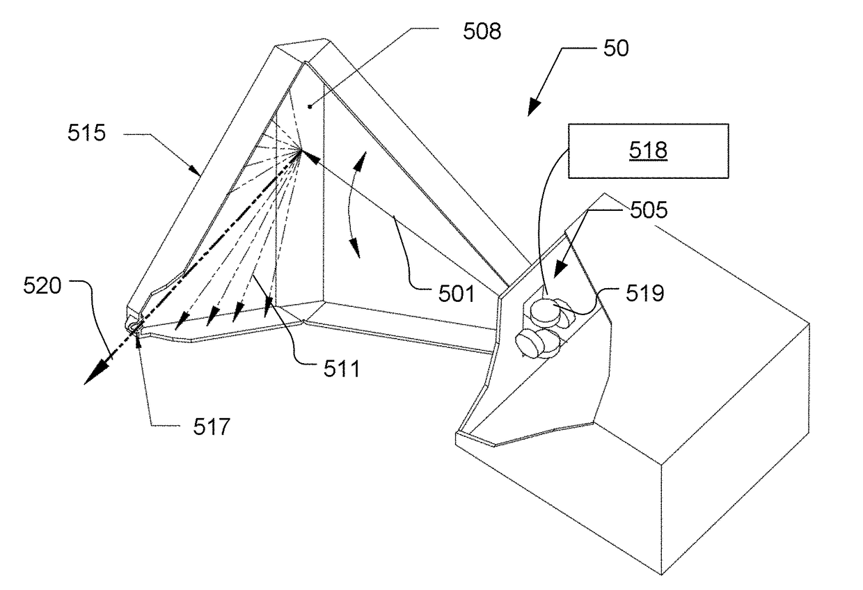
[0079]Inspectors may want enhanced images of a specific portion of all trucks. FIG. 6B shows the EMS scanning a 14 foot high tractor-trailer traveling at 12 kph at 7 feet distance from the snout 515 of the EMS 50. During the scan of the tractor, the beam height and intensity are easily adjusted to fit the size and maximum radiation dose. During the scan of the trailer, the single drive-by produces two independent views: a primary image of the entire trailer and an improved secondary image of the cargo in the bottom half of the trailer's interior. In this example, the semi has moved 3.3 mm during the 2 millisecond full sweep of the 14 foot height. The Rommel aperture 517 (shown in FIG. 5A), set at 1 mm diameter, produces stripes of pixels that are 7 mm wide. The odd numbered sweeps, called the Primary Sweeps along a Primary scan path 630, abut. The Primary sweeps alone produce an image of a fully scanned trailer. Alternating sweeps are now di...

example 2

Dual-Channel Snout to Improve Resolution

[0081]Snouts 720 of each of FIGS. 7B-7D have separate Rommel collimators 517 in each of two channels A and B, and can be used to obtain two independent views by alternating the scans of electron beam 501 such that that the odd-numbered x-ray beams 741 go through Channel A and the even numbered x-ray beams 742 go through Channel B, to produce different pixel energies, resolution or pixel intensity, as the case may be. Such a snout may be referred to as a “dual-channel snout,” or, alternatively, as a “two-channel snout.” Snouts with more than a single channel may be referred to as “multi-channel snouts.”

example 3

ng False Alarms from External Plastic

[0082]The backscatter (BX) inspection of vehicles, in the search for explosives or drugs, encounters serious difficulty distinguishing potential contraband inside the car's steel body from light element materials, such as plastic and carbon fiber, that may compose part of the outside of the vehicle. An EMS 50 in accordance with one of the embodiments of the present invention, may advantageously eliminate the false alarms by sending the ΔT(P) beams through channel A of FIG. 7B, and the alternate beams ΔT(S) through the channel B of FIG. 7B, which has a filter 750. Filter 750 may strongly absorbs x-rays below about 70 keV, for example. Thus, a car 108 may be scanned twice, where each scan is complete and provides spectral resolution. Comparing the intensity of the pixels in the image composed of x-rays through channel A, with the corresponding intensities in the image composed of x-rays through B, uniquely identifies whether a light element materia...


PUM


Abstract

Methods and an x-ray source for sweeping an x-ray beam across an object of inspection. A beam of electrons is emitted by a cathode, while a sweep controller applies a signal to a beam controller in a prescribed path on an anode, thereby causing an x-ray beam to be emitted from an aperture disposed at one apex of a snout of variable length. The aperture may be a Rommel aperture that allows for forming a scanning x-ray of desired size and flux independently of the angle at which the beam is emitted. Scanning rate may be varied during the course of a scan. Multiple x-ray beams may be formed simultaneously, where one beam is inside a conveyance while the other is outside the conveyance, for example.

Description

[0001]The present application claims the priority of U.S. Provisional Patent Application Ser. No. 62 / 216,783, filed Sep. 10, 2015, which is incorporated herein by reference.TECHNICAL FIELD[0002]The present invention relates to systems and methods for inspection of items using penetrating radiation, and, more particularly to inspection wherein a characteristic of the penetrating radiation is varied during the course of a single scan.BACKGROUND OF THE INVENTION[0003]Inspection of vehicles and containers by imaging backscattered radiation has, in the past, used mechanical means to create beams of x-rays that scan the targets. Various schemes for electromagnetically scanning x-ray beams are known as well, as taught, for example, in U.S. Pat. No. 6,249,567 (to Rothschild et al., 2001), which teaches the use of an electromagnetically scanned x-ray beam to scan the undercarriage of a vehicle.[0004]FIG. 1 shows a prior art X-ray backscatter system 100 where a source of x-rays 102 and a set ...

Claims


Application Information

Patent Timeline
IPC IPC(8): G01V5/00G01N23/20008
CPCG01V5/0025G01N23/20008G01N2223/639G21K1/02H01J35/153H01J35/14G21K5/10H01J35/30
Inventor GRODZINS, LEEDINCA, DAN-CRISTIANROMMEL, MARTIN
Owner AMERICAN SCI & ENG INC
Why Eureka
Try Eureka