Magnetohydrodynamic generator

a technology of magnetohydrodynamic generator and generator, which is applied in the field of magnetohydrodynamics, can solve the problem of retaining a large amount of residual energy

Active Publication Date: 2018-09-06
SAFRAN HELICOPTER ENGINES
View PDF12 Cites 7 Cited by
  • Summary
  • Abstract
  • Description
  • Claims
  • Application Information

AI Technical Summary

Benefits of technology

[0007]By means of these provisions, it is made easier to arrange the electrodes and the poles of the magnet along two axes that are substantially mutually perpendicular and perpendicular relative to the flow of the working fluid. In addition, it is possible to generate electricity from a portion only of the working fluid of a turbine, as may be desirable for example if the turbine is to deliver a relatively large amount of mechanical power, while the magnetohydrodynamic generator is for supplying significantly smaller amounts of electric power, for auxiliary purposes.
[0009]In order to accelerate the flow of fluid in the channel defined by the walls and the arms, thereby increasing the efficiency of the magnetohydrodynamic generator, the first and second walls may converge towards each other in the flow direction of the combustion gas over at least a first segment of the flow passage situated upstream from said pair of arms. Under such circumstances, and in order to avoid a large amount of reaction thrust, in particular when the magnetohydrodynamic generator is installed in an outlet nozzle of a turboshaft engine, in particular a turboshaft engine of a rotary wing aircraft, the first and second walls may diverge from each other in the flow direction of the working fluid over at least one second segment of the flow passage situated downstream from said pair of arms, so as to reduce the flow speed once more.
[0011]Relatively short distances between the opposite magnetic poles and electrodes in the channel defined by the pair of arms and the walls may be advantageous for the yield and the efficiency of the magnetohydrodynamic generator. In order to increase the quantity of working fluid used for magnetohydrodynamic generation, while limiting dimensions, the generator may include a plurality of pairs of arms, each connecting together the first and second walls downstream from said ionizing device, and for each pair of arms, it may include a respective magnet and a pair of electrodes. By splitting the magnetohydrodynamic generation of electricity among a plurality of channels, it is possible to increase electrical power while maintaining a small flow section for each channel. The pairs of electrodes in each channel may be connected together electrically in series or in parallel.

Problems solved by technology

Nevertheless, downstream from the turbine, the working fluid usually retains a large amount of residual energy.
Nevertheless, in practice, integrating such a magnetohydrodynamic generator in a turbine is not without drawbacks, in particular concerning the arrangement of the electrodes and the means for generating the magnetic field in a flow passage for the working fluid of the turbine.

Method used


Image

  • Magnetohydrodynamic generator
  • Magnetohydrodynamic generator
  • Magnetohydrodynamic generator

Examples


Embodiment Construction

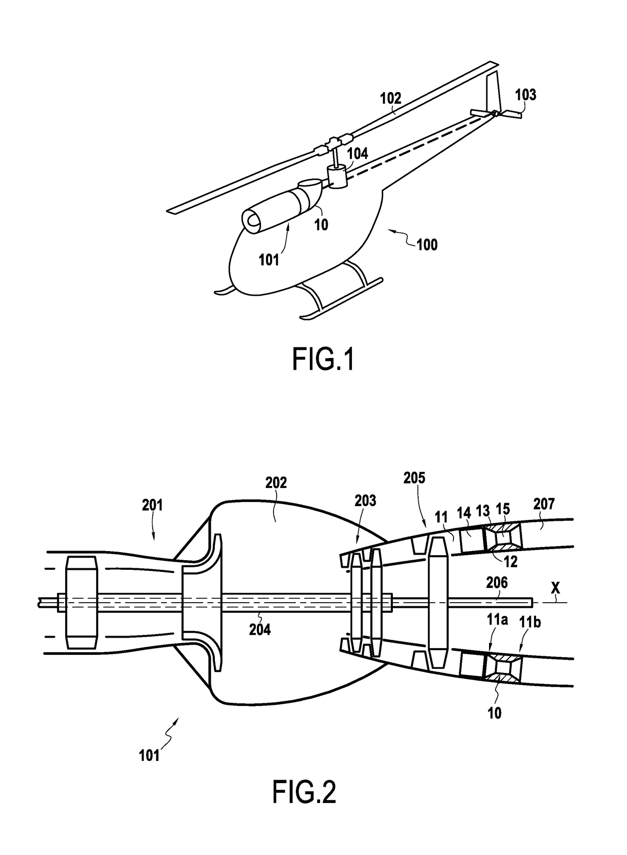
[0025]FIG. 1 shows a rotary wing aircraft, more precisely a helicopter 100, having a turboshaft engine 101 for driving its main rotor 102 and its tail rotor 103 via a transmission 104. The engine 101 includes an embodiment of a magnetohydrodynamic generator 10 for supplying electricity to the various electricity-consuming pieces of equipment on board the helicopter 1.

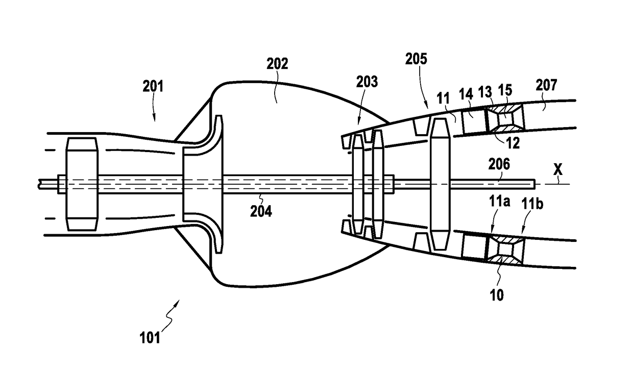
[0026]As shown in greater detail in FIG. 2, the engine 101 comprises a gas generator with, in the air flow direction: a compressor 201; a combustion chamber 202 having an igniter and injectors connected to a fuel supply system (not shown); and a first turbine 203 coupled to the compressor 201 via a first rotary shaft 204. Downstream of this second turbine 203, the engine 101 has a second turbine 205 coupled to a second rotary shaft 206, which in the helicopter 1 is suitable for coupling to the transmission 104 in order to drive the rotors 102 and 103. Finally, downstream from the second turbine 205, the engine includes ...


PUM


Abstract

The invention relates to the field of magnetohydrodynamic generators, and more precisely to such a generator (10) comprising a working fluid flow passage (11) that is defined by a first wall (12) and a second wall (13), an ionizing device (14) for ionizing the working fluid, a pair of arms (15), each connecting together the first and second walls (12, 13) downstream from said ionizing device (14) so as to define, within the flow passage (11), a channel (16) between said arms (15) and said walls (12, 13), said channel (16) being arranged to be traversed by a portion of the working fluid after it has been ionized, a magnet for generating a magnetic field (B) oriented in a direction that is perpendicular to the flow of the working fluid through the channel (16) defined by the pair of arms (15) and said walls (12, 13), and at least one pair of electrodes (17), each of the electrodes (17) in each pair being arranged on a respective side of the channel (16) defined by the pair of arms (15) and said walls (12, 13), said electrodes (17) in each pair being spaced apart from each in a direction that is perpendicular to said magnetic field (B) and to the flow direction of the working fluid through the channel (16) defined by the pair of arms (15) and by said walls (12, 13).

Description

BACKGROUND OF THE INVENTION[0001]The present invention relates to the field of magnetohydrodynamics, and in particular to its use for recovering at least a portion of the residual energy in the working fluid of a turbine.[0002]The term “turbine” is used to designate a rotary device that is designed to use the energy of a working fluid in order to cause a rotary shaft to rotate. The energy of the working fluid, characterized by its speed and its enthalpy is thus converted in part into mechanical energy that can be extracted by the rotary shaft. Nevertheless, downstream from the turbine, the working fluid usually retains a large amount of residual energy. In the description below, the terms “upstream” and “downstream” are defined relative to the normal flow direction of the working fluid.[0003]French patent application FR 2 085 190 already proposes using a magnetohydrodynamic generator in addition to a turbine for the purpose of recovering the energy contained in the working fluid of ...

Claims


Application Information

Patent Timeline
Patent Type & Authority Applications(United States)
IPC IPC(8): H02K44/12F01D15/10H02K44/10
CPCH02K44/12F01D15/10H02K44/10B64C27/04F05D2220/76H02K44/08H02K44/28
Inventor SERGHINE, CAMELKLONOWSKI, THOMASBEDDOK, STÉPHANERICHARD, STÉPHANE
Owner SAFRAN HELICOPTER ENGINES
Why Eureka
Try Eureka