
Flow pipe, and jet nozzle pipe and aerosol valve pipe using said flow pipe

a technology of flow pipe and jet nozzle, which is applied in the direction of liquid spraying apparatus, liquid dispensing, packaging, etc., can solve the problems of unstable ejection, failure in constant ejection, and discontinuous content ejection, so as to prevent ejection holes, excellent effects, and reliably stir

Active Publication Date: 2018-09-13
OGAWA OSAMU
View PDF11 Cites 3 Cited by
  • Summary
  • Abstract
  • Description
  • Claims
  • Application Information

AI Technical Summary

Benefits of technology

The present invention relates to a flow path tube and a jet nozzle tube that provide excellent effects such as stirring and mixing of fluids (liquid and gas) while preventing foreign substances from flowing out. The flow path tube includes a porous material that can be adjusted by its length, pores, and porosity to control the flow rate. The jet nozzle tube prevents clogging of its ejection holes and enables stable and constant ejection by the stirring and mixing action on fluids. The aerosol valve tube also prevents clogging and ensures stable and constant ejection. Overall, the technical effects of the present invention are improved mixing and prevention of clogging.

Problems solved by technology

Consequently, the content is ejected discontinuously and failure in stable ejection is a problem.
Consequently, failure in constant ejection amount is also a problem.
However, such researches are still midway.
However, a flow rate stabilizer cannot be mounted in a flow path tube, requires adjustments, and is complex in structure and expensive in product cost, thus not allowing everyone to realize stable ejection.
However, although yielding certain effect on stirring and mixing the content and the gas, the proposed techniques in the patent documents 1 and 2 cause foaming as a whole and fail to realize a completely stirred, and entirely uniformly mixed state.
Consequently, the content eventually ejected is not in perfect mist to the extent of floating in the air.

Method used


Image

  • Flow pipe, and jet nozzle pipe and aerosol valve pipe using said flow pipe
  • Flow pipe, and jet nozzle pipe and aerosol valve pipe using said flow pipe
  • Flow pipe, and jet nozzle pipe and aerosol valve pipe using said flow pipe

Examples


embodiment 1

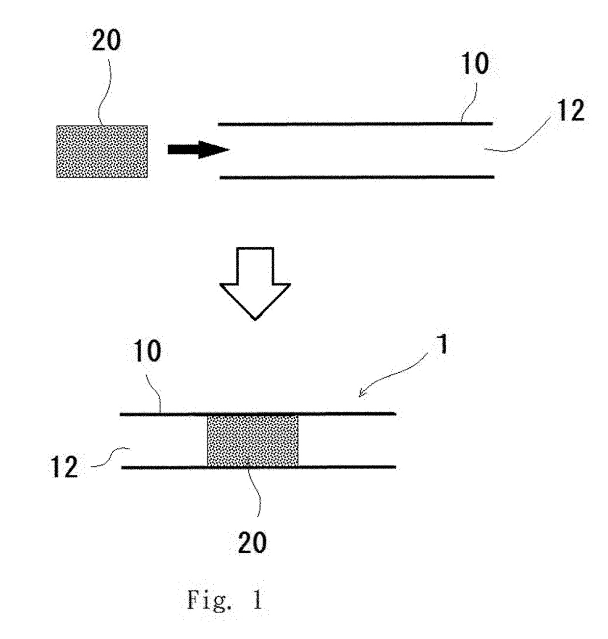
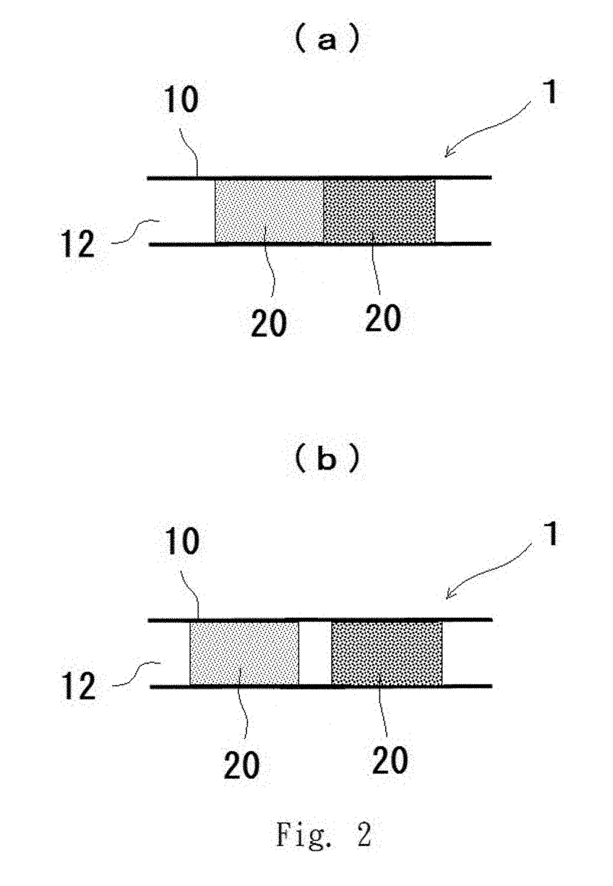
[0036]FIGS. 1 and 2 are cross-sectional views showing Embodiment 1 of the flow path tube 1 according to the present invention.

[0037]In other words, the flow path tube 1 according to this embodiment comprises the porous materials 20 at given positions within the tube channel 12 of the flow path tube body 10.

[0038]The material of the flow path tube 1 is not particularly restricted to metals or synthetic resins. The flow path tube 1 is made of, for example, LDPE (low density polyethylene). HDPE (high density polyethylene), fluororesin, nylon, polypropylene, PEEK (polyether ether ketone), or the like.

[0039]The porous material 20 is formed by a sintered body or foam of resin (polyethylene resin, polypropylene resin, polyurethane resin, phenol resin, polyvinyl chloride resin, urea resin, silicone resin, fluororesin, polyimide resin, and melamine resin) or ceramic or metal, has a continuous void structure and a necessary length, and has a necessary diametrical dimension enabling insertion ...

embodiment 2

[0052]FIGS. 3 and 4 are cross-sectional views showing Embodiment 2 of the flow path tube 1 according to the present invention.

[0053]In other words, the flow path tube 1 according to this embodiment comprises the porous material 20 within the tube channel 12 of the flow path tube body 10 and is different from the above Embodiment 1 in that the porous material 20 comprises an insert part 22 that is inserted into the tube channel 12 and a leading end part 24 that is not inserted into the tube channel 12 and exposed and that the insert part 22 of the porous material 20 is inserted from an leading end 10a of the flow path tube body 10 and fixed within the tube channel 12.

[0054]The porous material 20 comprises the insert part 22 and the leading end part 24. The insert part 22 has a necessary length and a necessary diametrical dimension enabling insertion into the tube channel 12 of the flow path tube body 10. The length of the insert pan 22 is not particularly restricted. However, this le...

embodiment 3

[0064]FIG. 5 is a cross-sectional view showing a first embodiment of the jet nozzle tube 14 according to the present invention.

[0065]In other words, the jet nozzle tube 14 according to this embodiment uses the flow path tube 1 according to the above Embodiment 1, namely the flow path tube 1 comprising the porous material 20 at a given position within the tube channel 12, in which ejection holes 18 are formed at given positions in the flow path tube body 10.

[0066]Here, the jet nozzle tube 14 is the flow path tube 1 that is connected at the base end 10c to a valve body provided at the upper end of a spray can or an aerosol can and comprises the ejection holes 18 near the leading end 10a for ejecting the content of the spray or aerosol can from the ejection holes 18.

[0067]The flow path tube body 10 according to this embodiment is closed at the leading end 10a and sprays the fluids (a liquid and a gas) from the formed ejection holes 18. The ejection holes 18 are formed in either one or ...


PUM


Abstract

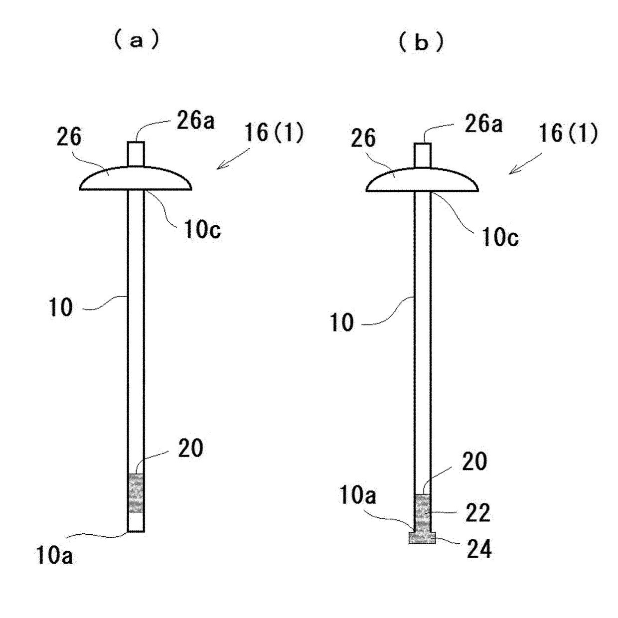
[Problem] To provide a flow path tube that prompts gas / liquid stirring of fluids flowing through a tube channel, enables adjustment of the flow rate, and furthermore suppresses passage of foreign substances.[Solution means] A flow path tube 1 is configured by inserting and disposing within a tube channel 12 of a flow path tube body 10 at least one or more porous materials 20 having a continuous void structure and a necessary length / a necessary diametrical dimension. Moreover, at least one or more ejection holes 18 are formed at given positions in the flow path tube body 10 or in the porous material 20 to form a jet nozzle tube 14 using the flow path tube 1. Furthermore, a valve body 26 is attached to the base end 10c of the flow path tube body 10 to form an aerosol valve tube 16 using the flow path tube 1.

Description

TECHNICAL FIELD[0001]The present invention relates to a flow path tube within the tube channel of which fluids flow and further relates to a jet nozzle tube and an aerosol valve tube using the flow path tube.BACKGROUND ART[0002]In structures for spray / aerosol, a spray can or an aerosol can contains, in addition to a content, liquefied gas such as LPG and butane or gas such as nitrogen, carbon dioxide, and air for ejecting the content. The content is ejected from a jet nozzle provided at an upper part of the can via an aerosol valve tube disposed in the can. Alternatively, a nozzle tube is further attached to the jet nozzle and the content is ejected from an ejection outlet provided at the leading end of the nozzle tube.[0003]In ejecting the content in such a spray can or an aerosol can, the content and the gas are separated and ejected alternately. Consequently, the content is ejected discontinuously and failure in stable ejection is a problem.[0004]Moreover, the amount of ejected c...

Claims


Application Information

Patent Timeline
IPC IPC(8): B65D83/32B05B9/04B65D83/14
CPCB65D83/32B05B9/04B65D83/14B05B7/0491B65D83/303B05B15/20
Inventor OGAWA, OSAMU
Owner OGAWA OSAMU
Learn More