Floating moon pool hydraulic pump

a technology of hydraulic pump and moon pool, which is applied in the direction of liquid fuel engines, machines/engines, vessel construction, etc., can solve the problems of reducing the effect of oscillating water levels, exposing the working mechanism to potential damage, and reducing the impulses of the pump, so as to capture the pure vertical action and reduce the impulses

Inactive Publication Date: 2018-09-13
GORMAN THOMAS GREGORY
View PDF8 Cites 5 Cited by
  • Summary
  • Abstract
  • Description
  • Claims
  • Application Information

AI Technical Summary

Benefits of technology

[0008]While other devices have been developed with the goal to capture and convert wave energy, embodiments of the present invention have several distinct advantages over previous concepts. For example, in contrast to previous systems using mechanical linkages, the apparatus described herein uses waves to create a potential energy whereby the weight of a floater pumps a fluid. Because the pressurization of the water driven to the turbines is purely gravity induced, there is no mechanical loss of energy through linkages or rotating components and the pressure loss of the fluid in route to the turbine is minimal.
[0009]Known devices may use a fixed structure or anchoring to the sea floor, while embodiments of the present invention may use the inertia of a large floating vessel. This provides an added benefit as electricity can be generated at the on-site platform rather than pumping fluid a long distance to turbine-generators on land.
[0010]Still other known devices pump on the upstroke with swell action or are bi-directional. Instead, embodiments of the present invention pump using gravity on the down stroke. Because a passing wave shall elevate a plurality of floaters and a lag time is expected in transferring fluid through a turbine, the present invention is able to develop a constant pressure, which acts as a reservoir to reduce impulses on the system.
[0011]Further, other known devices expose the working mechanism to potential damage from wind, waves or debris. Embodiments of the present invention may be configured to protect the working mechanism from the lateral and slamming forces of waves in the open sea and is thus more effective at capturing the pure vertical action of a passing wave.
[0012]Embodiments of the present invention offer additional advantages. First, the present invention may be a single unit capable of producing a large quantity of power if situated in the proper ocean environment whereas known devices often consist of numerous small units aimed at capturing the energy from tidal waves. These typically produce little electricity per individual unit and are spread out over large swaths of shoreline with many cables extending to one another or back to land. This can be undesirable to local residents and wildlife. The apparatus described herein would typically be situated a significant distance offshore due to the vessel draft and would only require a single electrical cable extending to a substation on land.
[0013]Next, embodiments of the present invention may comprise a significant number of components that are regularly found on existing ships, which can prove beneficial over an innovative concept where feasibility and constructability are unknown. The construction of a vessel in accordance with the present invention could be very similar to that of an oil tanker but simpler to a degree. Because the vessel is intended to be stationary it can be made “boxier” with constant angles and facets at the forward and aft end rather than having complex curvature and bulbous bows used to reduce the drag of mobile vessels. Also, for a stationary setting, there would be no need for a propulsion system, which reduces cost in comparison to an oil tanker.

Problems solved by technology

Previously, the oscillation of waves within these moon pools has been seen as detrimental and efforts have been made to dampen the effect of oscillating water levels within such moon pools.
Further, other known devices expose the working mechanism to potential damage from wind, waves or debris.
This can be undesirable to local residents and wildlife.

Method used


Image

  • Floating moon pool hydraulic pump
  • Floating moon pool hydraulic pump
  • Floating moon pool hydraulic pump

Examples


Embodiment Construction

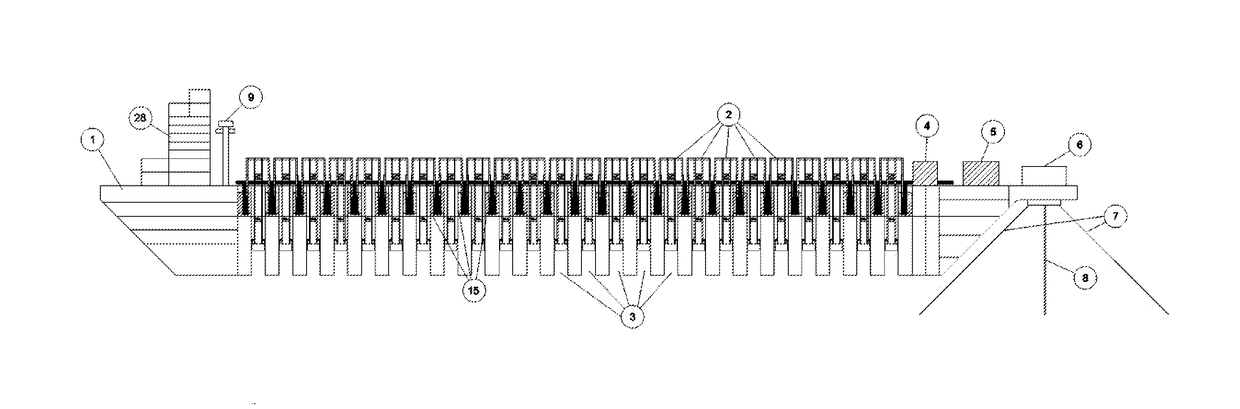
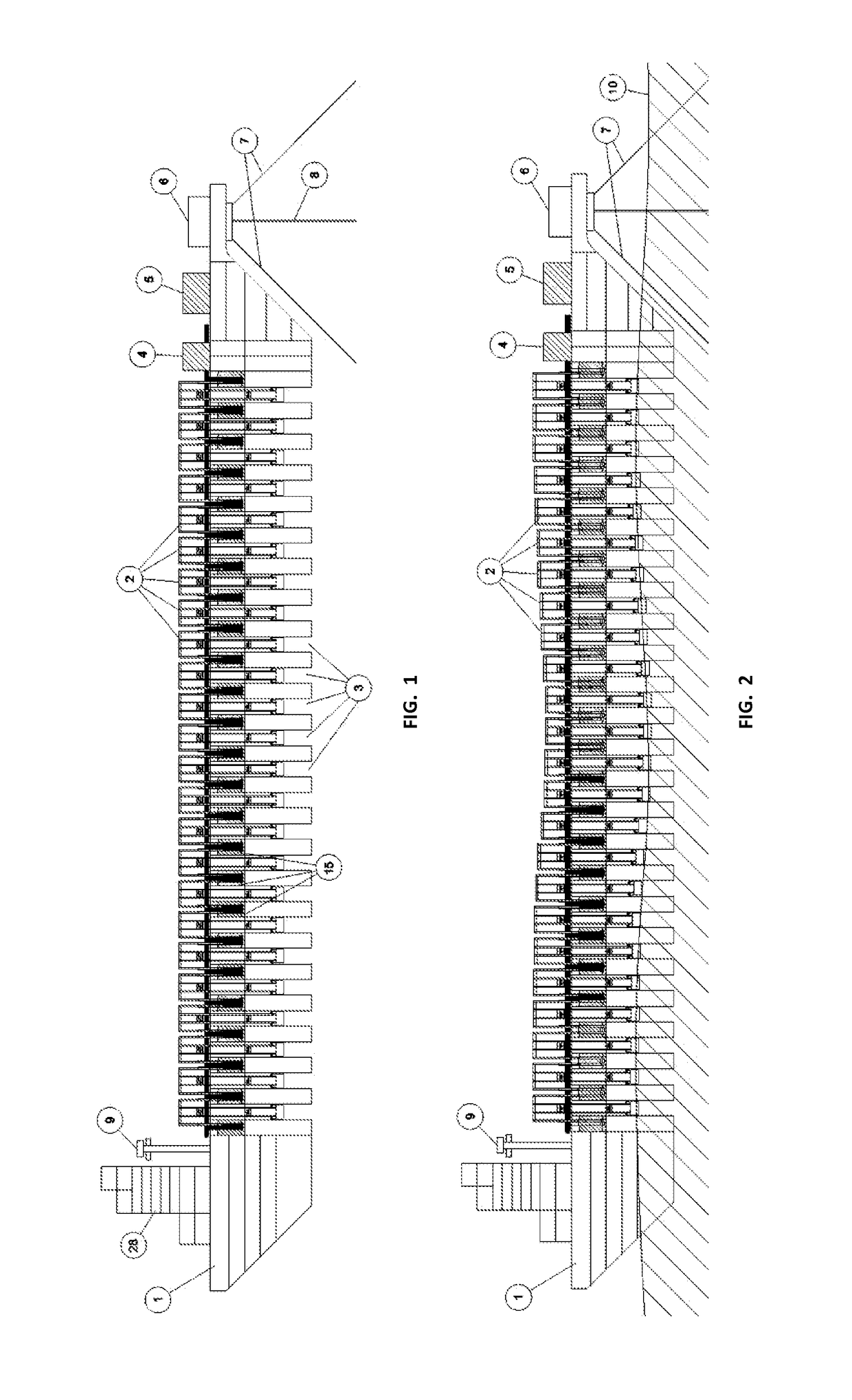
[0053]Referring now to embodiments of the invention in more detail, as illustrated in FIG. 1 and FIG. 2, the apparatus comprises a floating vessel 1, multiple pump units 2, multiple moon pools 3, hydro-electric turbines 4, electrical module 5, turret 6, mooring lines 7, subsea electrical cables 8 and gantry crane 9. Throughout this application, the words “vessel” or “ship” may be used to describe embodiments of the present invention. However, it should be noted that any appropriate platform or other support structure may be used, including ships, boats, hulls, watercraft, buoys, floats, barges, modified offshore oil platforms or the like. FIG. 1 is illustrated with the pumping units 2 in a stationary position as may occur in a calm sea. FIG. 2 is illustrated with a passing wave 10 to demonstrate the vertical pumping action.

[0054]The apparatus depicted in FIG. 1 and FIG. 2 may capture a portion of the energy within a passing wave 10 and convert it to electrical energy via hydroelectr...


PUM


Abstract

The invention comprises a hydraulic pump, wherein wave energy is used to pump a fluid. The apparatus utilizes the oscillation of the free surface of a water column within a moon pool on a floating vessel to lift a floating pump unit. After reaching a peak elevation induced by a passing wave, the gravitational forces on the floater pressurizes and moves a fluid using structurally linked pistons within fixed cylinders on the vessel during the downward return motion of the floater. The pressurized fluid can then be used in a variety of applications including the generation of electricity via hydroelectric turbines.

Description

FIELD OF THE INVENTION[0001]The present invention relates to energy conversion and electrical power generation. More particularly, the present invention relates to ocean wave powered hydraulic pumps and hydroelectric power production.SUMMARY OF THE INVENTION[0002]Embodiments of the present invention include a unique floating ship-type apparatus with the means to capture a portion of the energy within a passing wave to pump a fluid for the use of electrical generation or other useful process. The apparatus utilizes the vertical oscillation of the free surface of seawater within a moon pool (an open column within the structure of a vessel open to the sea below and atmosphere above) to lift a floating pump unit as wave crests pass by the ship. The floating pump unit includes structurally linked pistons that translate within fixed piston cylinders on the vessel. As the wave lifts the floating pump unit, a low pressure fluid fills the volume of the piston cylinders via check or single-di...

Claims


Application Information

Patent Timeline
Patent Type & Authority Applications(United States)
IPC IPC(8): F03B13/20F04B53/10F03B15/08F01D15/10B63B35/44B63B3/14B63B21/50
CPCF03B13/20F04B53/10F03B15/08F01D15/10B63B35/44B63B3/14B63B21/507B63B2035/4466B63B2003/147F03B13/187F03B13/1875F05B2240/40F05B2240/931Y02E10/30
Inventor GORMAN, THOMAS GREGORY
Owner GORMAN THOMAS GREGORY
Why Eureka
Try Eureka