Air intake structure and airflow control system

a technology of air intake structure and airflow control system, which is applied in the direction of air-flow influencers, power plant arrangements/mounting, de-icing equipment, etc., can solve the problems of general decrease in aerodynamic efficiency of aircraft, parasite drag generation, and efficiency decline, so as to reduce drag

Inactive Publication Date: 2018-09-20
YOUSEF HANI M SAEED
View PDF0 Cites 10 Cited by
  • Summary
  • Abstract
  • Description
  • Claims
  • Application Information

AI Technical Summary

Benefits of technology

[0008]The present invention relates to an air intake structure exposable to an airflow, for use on an aircraft having a fuselage, wings and engines. At least one of the engin...

Problems solved by technology

Parasite drag can be generated by the shape of the aircraft, which results from the direct contact of the aircraft with the airflow.
Drag generally d...

Method used


Image

  • Air intake structure and airflow control system
  • Air intake structure and airflow control system
  • Air intake structure and airflow control system

Examples


Embodiment Construction

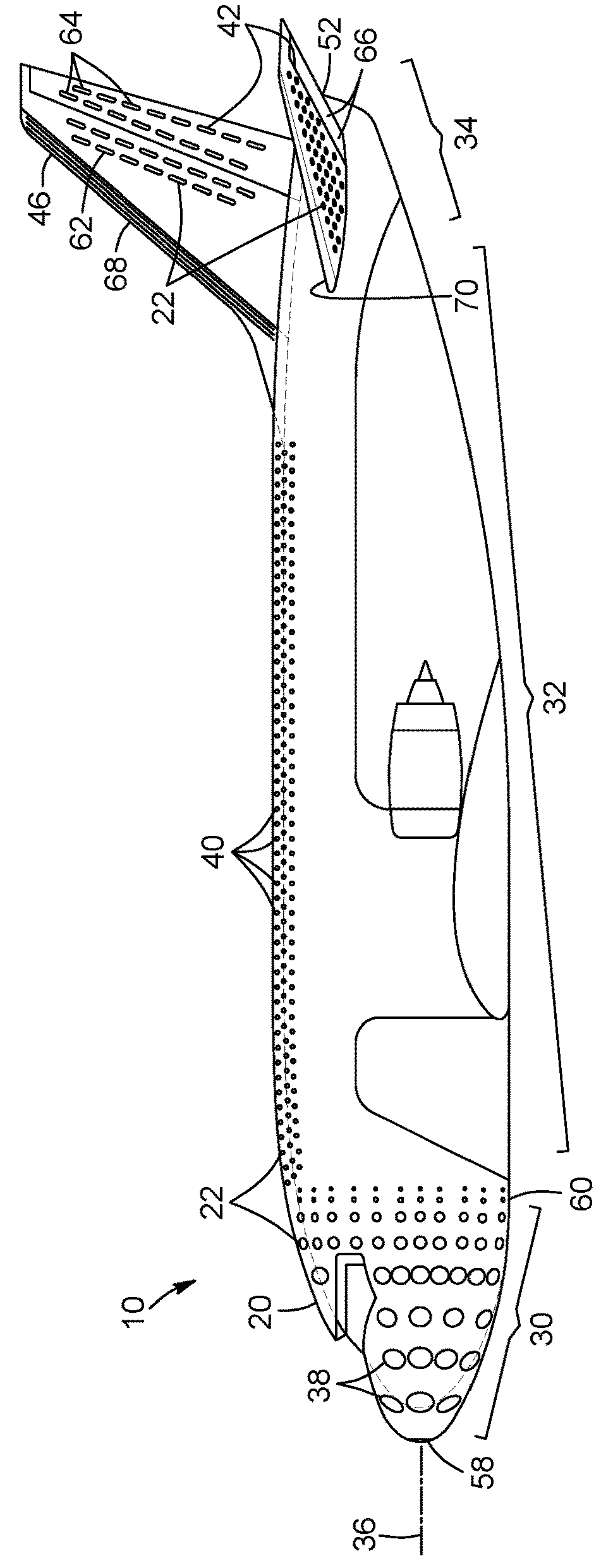
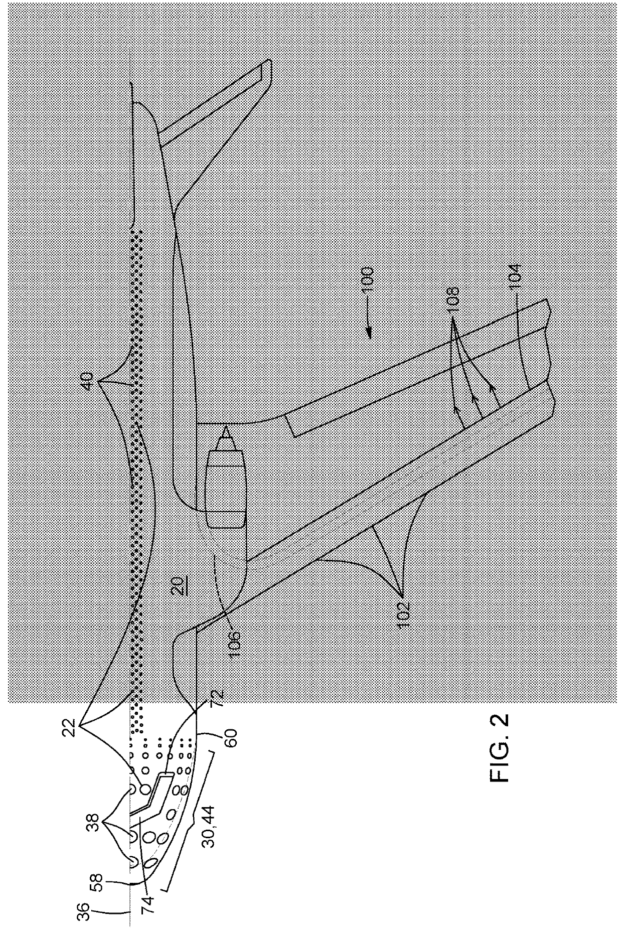
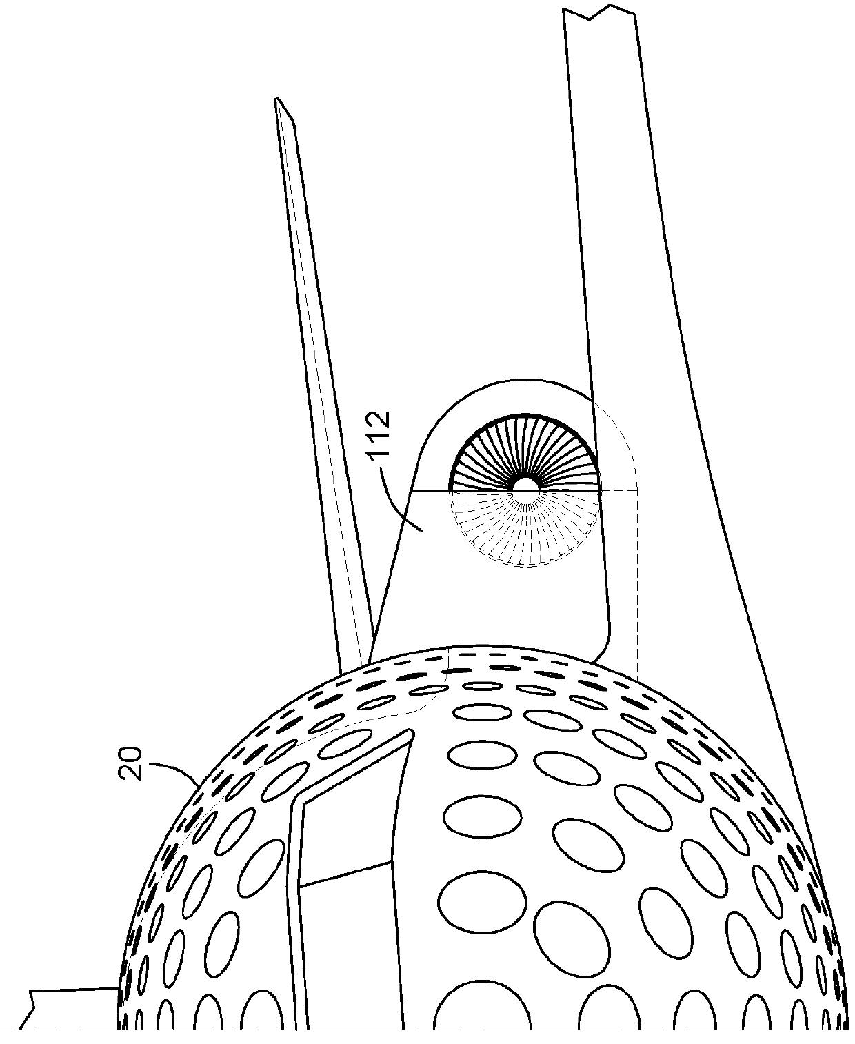
[0048]Referring to FIG. 1, there is shown an aircraft having a fuselage, wings and engines. Each engine has an air intake area corresponding approximately to a frontal area of the engine. Preferably, the engines are mounted on top of the wings and in close proximity with the fuselage of the aircraft, as shown in FIG. 1.

[0049]Still referring to FIG. 1 and to FIGS. 6A and 6B, there is shown an aircraft with an air intake structure 10, exposed to an airflow 12, for reducing drag and assisting aerodynamic control surfaces in controlling the aircraft. The air intake structure 10 refers to a structure designed to receive ambient air or airflow 12 and to direct such air towards the aircraft engines as air intake. The air intake structure 10 is also designed to supply the engines with the required intake air. A difference between the present invention and the prior art is shown in FIGS. 6A and 6B. According to the prior art, the outer fuselage of the aircraft moving with a given velocity co...


PUM


Abstract

An aircraft design using an air intake structure for reducing drag and assisting aerodynamic control surfaces in controlling the aircraft. The air intake structure comprises an outer skin including a plurality of perforations, a plurality of closing plates for covering corresponding perforations and an actuator operatively connected to the plurality of closing plates. The outer skin creates a chamber between the outer skin and a fuselage of the aircraft and extends to cover engines of the aircraft and adapted to restrict airflow into the engines. The plurality of closing is movable between a closed position covering the corresponding perforations and, an open position, uncovering the corresponding perforations. The actuator is used for positioning the plurality of closing plates between the closed position and the open position. The aircraft design also includes a wing for minimizing an airfoil boundary layer separation and de-icing a leading edge of the wing.

Description

FIELD OF THE INVENTION[0001]The present invention relates to aircraft design. More particularly, the present invention relates to an air intake structure absorbing and directing airflow into engines of an aircraft for reducing drag on the aircraft.BACKGROUND OF THE INVENTION[0002]Drag is an aerodynamic force that opposes an aircraft's motion through the air and can be generated by every part of the aircraft.[0003]Drag is generally generated by the interaction and contact of a solid body, such as an aircraft, with a fluid, such as air. In aircraft design, drag is generally a function of aircraft configuration, altitude and speed. Drag is also known to increase exponentially with speed, therefore if the aircraft speed is doubled, the drag force will be quadrupled.[0004]Among the drag forces acting on the aircraft, two forms of drag relate to the aircraft configuration and are known as parasite drag and interference drag. Parasite drag can be generated by the shape of the aircraft, whi...

Claims


Application Information

Patent Timeline
IPC IPC(8): B64D33/02B64C21/08B64C21/06B64D15/04B64D27/18B64C21/04
CPCB64D33/02B64C21/08B64C21/06B64D15/04B64D27/18B64C21/04B64D2033/0226B64D27/20Y02T50/10B64C21/01
Inventor YOUSEF, HANI M. SAEED
Owner YOUSEF HANI M SAEED
Why Eureka
Try Eureka