

Split cycle engine with crossover shuttle valve
a technology of shuttle valve and split cycle engine, which is applied in the direction of valve arrangement, combustion engine, machine/engine, etc., can solve the problems of reducing engine efficiency and revealing how to effectively
- Summary
- Abstract
- Description
- Claims
- Application Information
AI Technical Summary
Benefits of technology
Problems solved by technology
Method used
Image

Examples
Embodiment Construction
[0153]The principles, uses and implementations of the teachings herein may be better understood with reference to the accompanying description and figures. Upon perusal of the description and figures present herein, one skilled in the art is able to implement the teachings herein without undue effort or experimentation. In the figures, like reference numerals refer to like parts throughout.
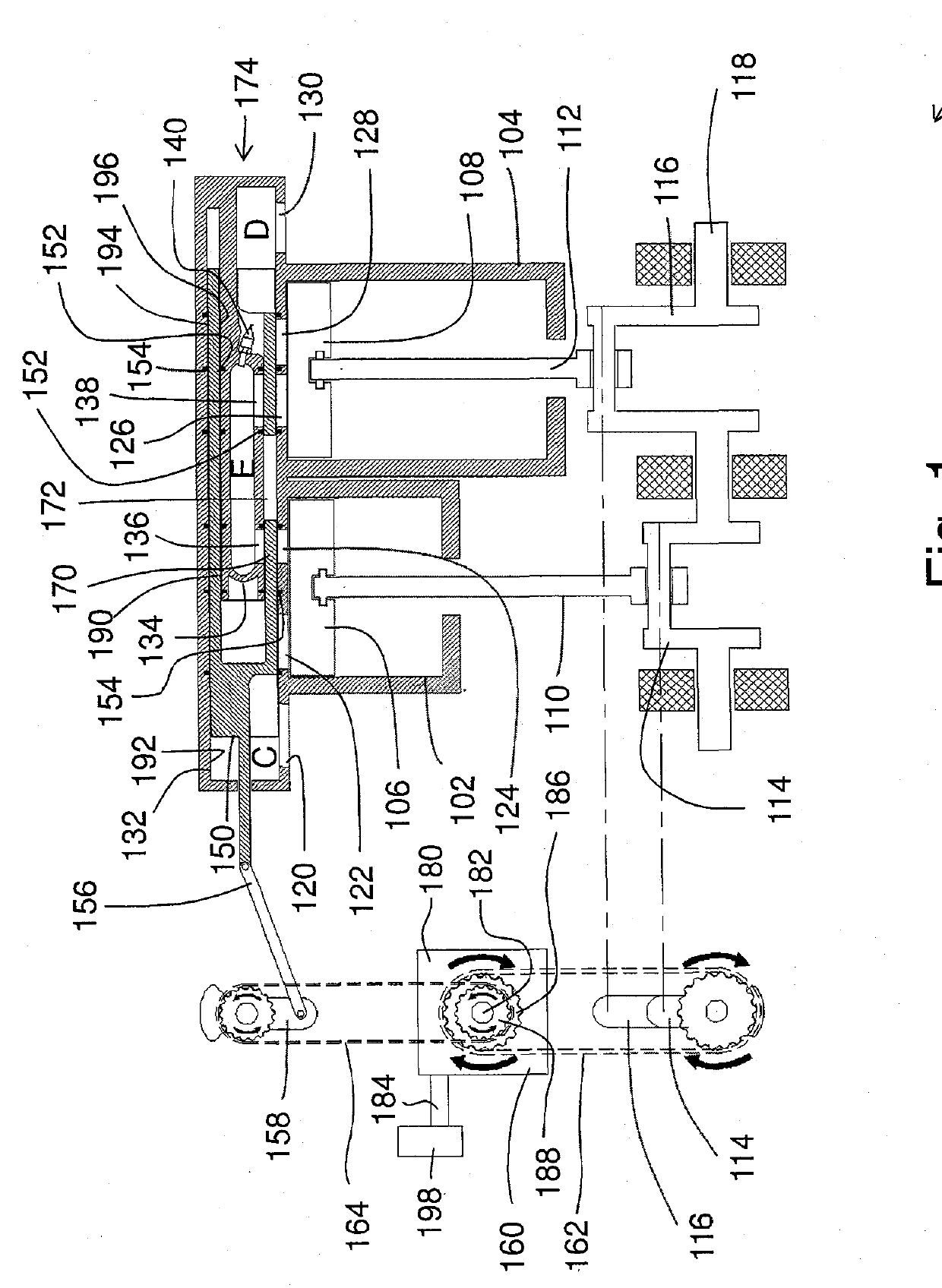
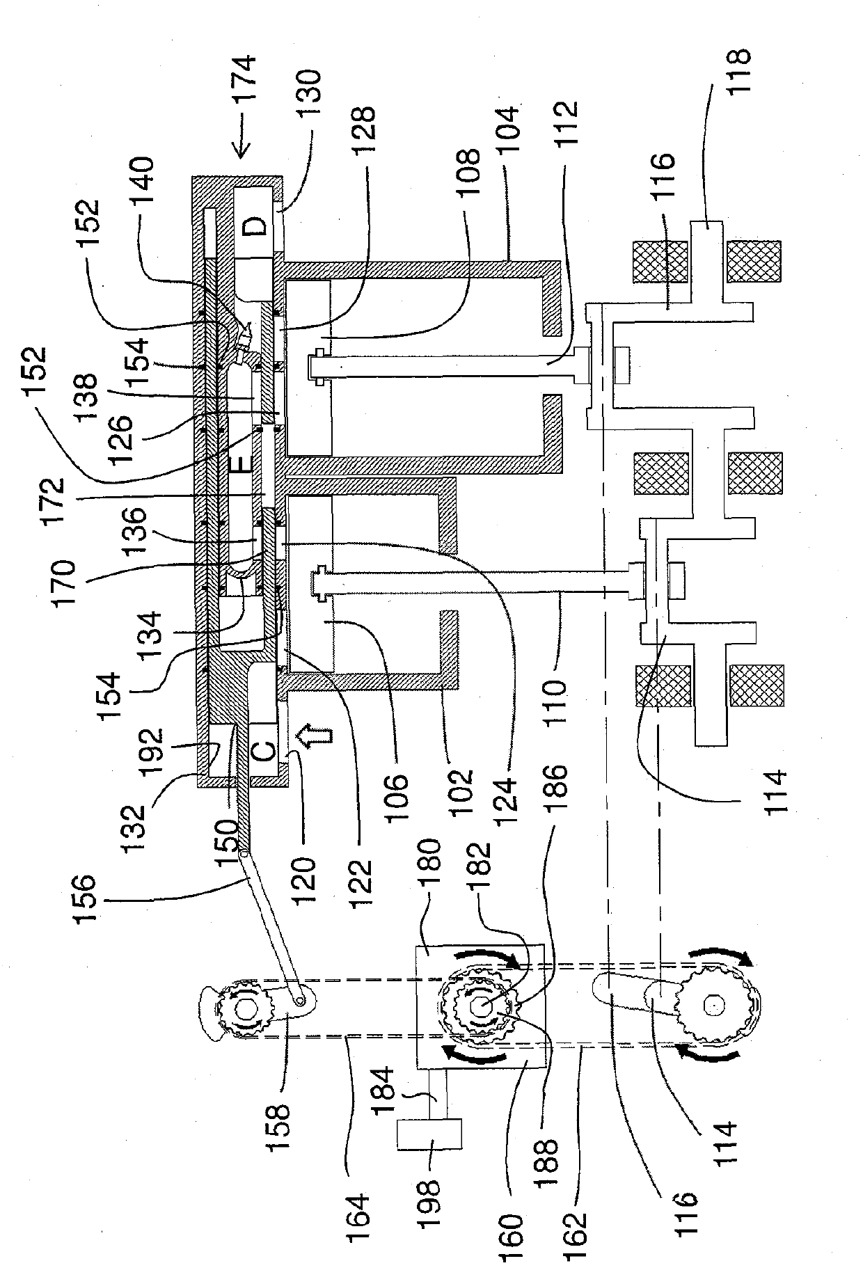
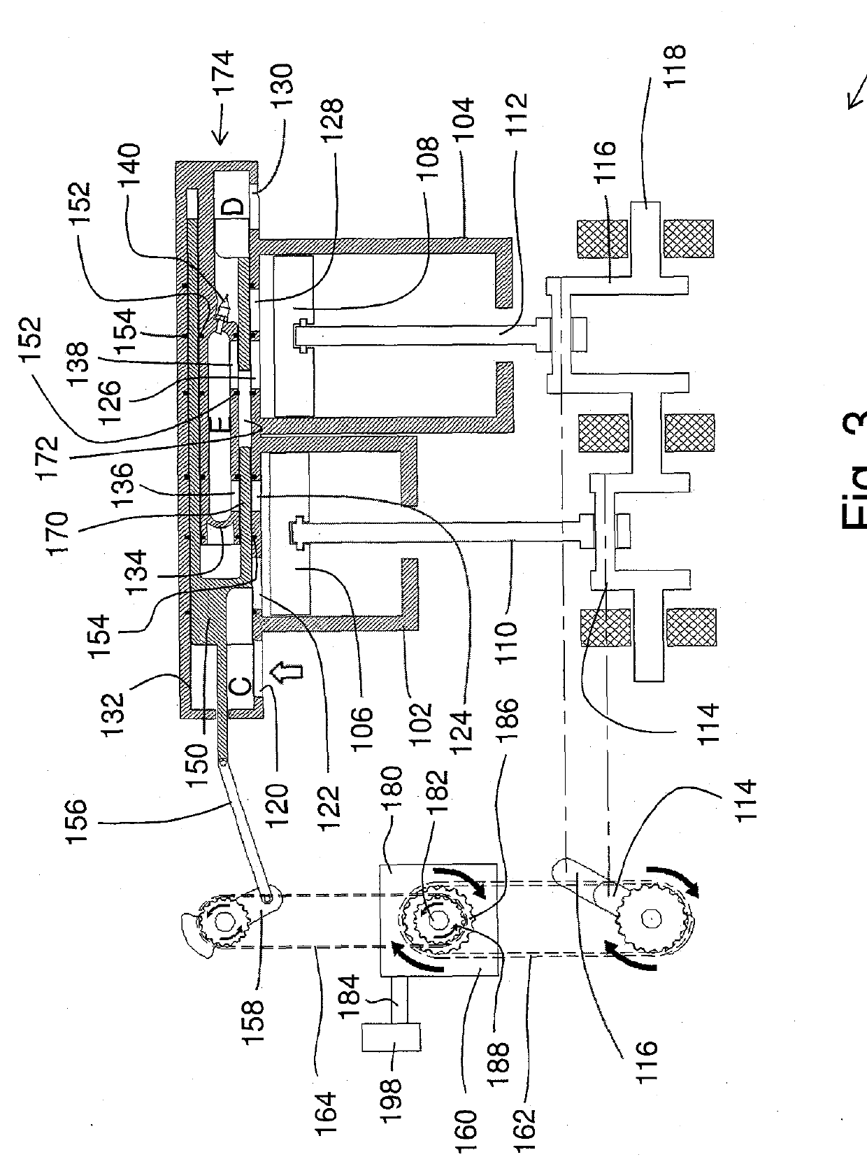
[0154]In-Line Configuration of a Split-Cycle Engine
[0155]Referring to FIGS. 1-17, in accordance with one embodiment, an in-line configuration of a split-cycle engine 100 includes: a first cylinder 102, a second cylinder 104, a first piston 106, a second piston 108, a first chamber A defined between first cylinder 102 and first piston 106 (shown in FIGS. 4-14, 20-30, 36-46, 52-62), and a second chamber B defined between second cylinder 104 and second piston 108 (shown in FIGS. 4-14, 20-30, 36-46, 52-62). The split-cycle engine also includes a first piston connecting rod 110, a second piston connect...
PUM
 Abstract
Description
Claims
Application Information