Connecting Structural Member

a structural member and connecting technology, applied in the direction of fastening means, construction elements, threaded fasteners, etc., can solve the problems of re-tapping the nut, high energy consumption of welding, and generating thread deformation within the nuts, so as to improve the connection strength with the receiving structure, reduce the amount of cutting, and improve manufacturing efficiency.

Inactive Publication Date: 2018-09-20
PENN ENG & MFG CORP
View PDF12 Cites 0 Cited by
  • Summary
  • Abstract
  • Description
  • Claims
  • Application Information

AI Technical Summary

Benefits of technology

[0020]The insert of the present disclosure allows a simple external installation that not only improves the connection strength with the receiving structure, but also reduces

Problems solved by technology

Welding has high energy consumption and may easily generate thread deformation within the nuts during the welding process.
This requires re-tapping the nut and increases costs.
Moreover, for aluminum and other materials, the welding process is poor in quality and may produce welding defects easily which adversely influences the effect of fastened connection.
On the other hand, with riveting the connection strength and reliability attaching nuts is low.
Furthermore, riveting cannot be used where there is limited access to the backside of the pl

Method used


Image

  • Connecting Structural Member
  • Connecting Structural Member
  • Connecting Structural Member

Examples


embodiment 1

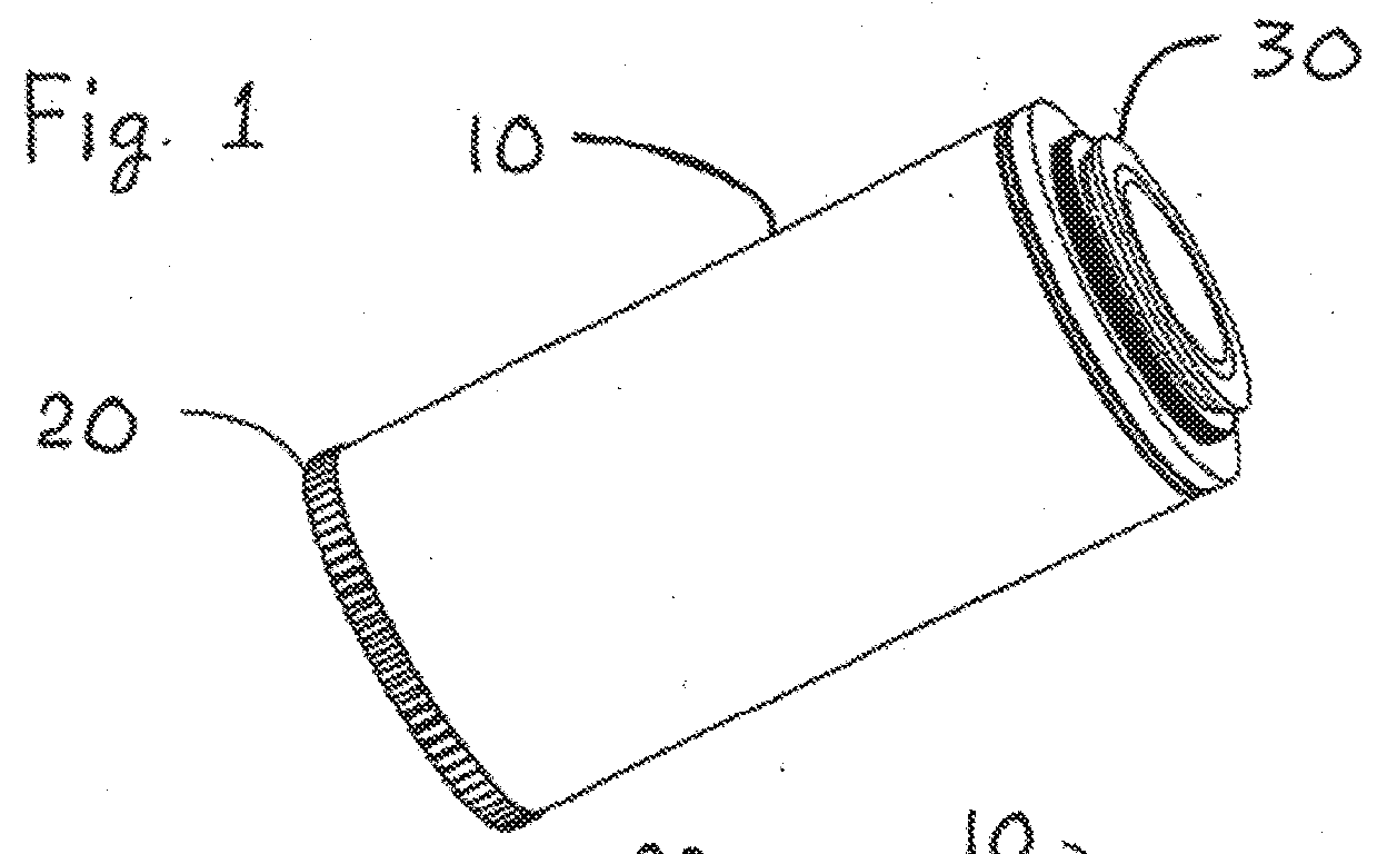
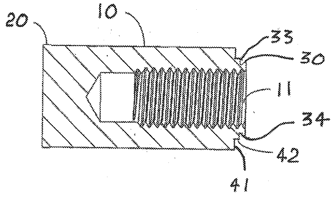
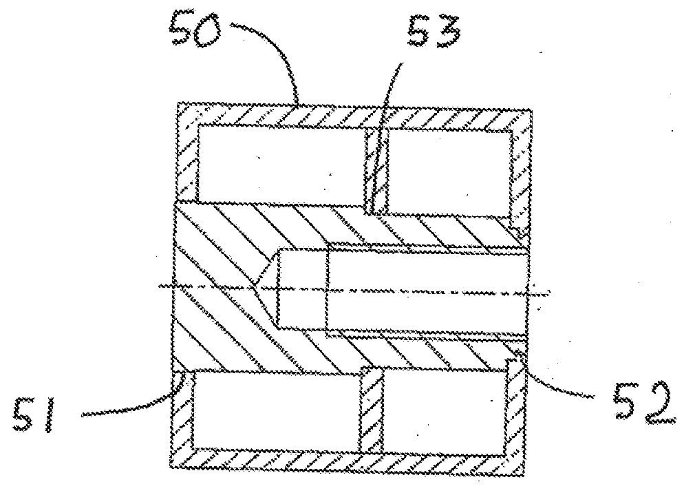
[0031]An insert providing a reinforced connecting structural member according to one embodiment of the invention is shown in FIGS. 1-4. In FIG. 3 we see the insert mounted into a receiving structure 50 having at least two parallel members with surfaces for fastened connection. As seen in FIG. 1, the insert comprises a cylinder 10 having a first end and a second end opposite to the first end; a first spline 20 disposed at the first end, wherein the first spline 20 is arranged circumferentially on an outer surface of the cylinder 10. The insert has a clinch 30 disposed at the second end of the cylinder 10 and circumferentially around the cylinder 10. The first spline 20 and the interlocking clinch 30 are respectively fastened to two parallel surfaces of the receiving structure 50, and at least one of the first and second ends of the cylinder 10 is fastened to a fitting member 61 through a connecting member as shown in FIG. 4. In the present disclosure, the first spline 20 is fitted to...

embodiment 2

[0036]An insert is also provided in another embodiment. As best shown in FIGS. 5 and 6, the structural member of this embodiment differs from that of the above embodiments in that, double-sided blind holes are disposed at both ends of the cylinder 10, i.e., the cylinder 10 has a first blind hole 12 and a second blind hole 13 at its inside, so that the receiving structure 50 may be connected to the fitting members 61 on both ends of the cylinder 10 through the first blind hole 12 and the second blind hole 13, respectively. The axial hole 11 may be one of a threaded through hole, an unthreaded blind hole, an unthreaded through hole, a half threaded hole, an unthreaded step hole.

embodiment 3

[0037]An insert is also provided in another embodiment. As best shown in FIGS. 7 and 8, the structural member of the present embodiment differs from those of the above embodiments in that, at least one of the two ends of the cylinder 10 has a connecting rod 14 extending axially from the cylinder 10, which may be an unthreaded rod or a threaded rod. In other words, in the present embodiment, the connection between the cylinder 10 and the fitting members 61 is realized through the connecting rod 14, and the corresponding connecting member may be replaced with a mating nut or the like.

[0038]In view of the above, the reinforced connecting insert provided by the present description can be used for connecting a receiving structure having at least two parallel surfaces to a fitting member. The insert includes a cylinder having a first end and a second end opposite to the first end; a first spline disposed at the first end of the cylinder, wherein the first spline is arranged circumferentia...


PUM


Abstract

An insert for connecting to a receiving structure having at least two parallel members includes having a first end and a second end opposite to the first end; a first spline disposed at the first end of the cylinder, wherein the first spline is arranged circumferentially on an outer surface of the cylinder; and an interlocking clinch disposed at the second end of the cylinder and circumferentially around the cylinder; wherein the first spline and the interlocking clinch are respectively fastened to two parallel members of the structure, and at least one of the first and second ends of the cylinder is fastened to a fitting member through a connecting member. The first spline can be fitted to one member of the structure with interference, and the interlocking clinch is self-fastened with another member of the structure due to material flow.

Description

FIELD OF THE INVENTION[0001]The present disclosure generally relates to metal-working fastening technology. More particularly, it relates to a reinforcing connecting structural member for connecting objects to parallel plates.BACKGROUND OF THE INVENTION[0002]When attaching objects to plates which do not lend themselves to direct thread tapping, there are two conventional fastening methods which connect threaded fasteners such as nuts to plates so that other fitting members can be fastened to the plate. One is welding, and the other is riveting. Welding has high energy consumption and may easily generate thread deformation within the nuts during the welding process. This requires re-tapping the nut and increases costs. Moreover, for aluminum and other materials, the welding process is poor in quality and may produce welding defects easily which adversely influences the effect of fastened connection. On the other hand, with riveting the connection strength and reliability attaching nu...

Claims


Application Information

Patent Timeline
IPC IPC(8): F16B37/12F16B4/00
CPCF16B37/122F16B4/004F16S3/06F16B5/0275F16B37/065
Inventor NI, PENGDUAN, DAPENGZHANG, MING
Owner PENN ENG & MFG CORP
Why Eureka
Try Eureka