Vacuum Pump Systems For Prosthetic Limbs And Methods Of Using The Same

a technology of vacuum pump and prosthetic limb, which is applied in the field of suspension systems for prosthetic limbs, can solve the problems of wasting time, affecting the operation efficiency of the pump system, and the inability of mechanically activated pumps to provide initial air evacuation without effort, etc., and achieves the optimization of the size and capacity of the components used, improve the efficiency of the pump system, and improve the effect of the performance of the pump system

Active Publication Date: 2018-09-27
THE GOVERNMENT OF THE UNITED STATES OF AMERICA AS REPRESENTED BY THE DEPT OF VETERANS AFFAIRS +1
View PDF0 Cites 2 Cited by
  • Summary
  • Abstract
  • Description
  • Claims
  • Application Information

AI Technical Summary

Benefits of technology

[0016]The mechanically activated pumps of the present disclosure may utilize first and second compression members, with a diaphragm disposed therebetween and coupling elements disposed about an outer perimeter of the diaphragm. The coupling elements permit relative translation of the compression members, which maintain a parallel relationship while compressing the diaphragm or permitting it to expand to its resting state.
[0017]To further enhance the performance of pump systems for suspension of a prosthetic limb, the present disclosure also provides pump systems that include an electrically activated pump, such as of the micro pump type utilized in exclusively electrical systems, and in the hybrid system disclosed in U.S. patent application Ser. No. 13 / 529,833, thereby providing a modular hybrid system. A hybrid pump system of the present design may offer a more efficient hybrid system, while still providing the significant advantages of the prior hybrid system. Such advantages include the desired rapid engagement upon initial donning of the prosthetic device, while not requiring solely battery power to evacuate air and to maintain appropriate vacuum levels. The more efficient design of the mechanically activated pump may permit longer intervals between charging of rechargeable batteries or battery packs, or between replacement of disposable batteries.
[0018]A hybrid system of the present diaphragm design also may provide for better optimization of the size and capacities of the components utilized. The new design for the mechanically activated pump portion of a hybrid system need not be as concerned with the ability to rapidly establish large capacity initial evacuation solely via the mechanically activated pump, because of the assistance of an electrically activated pump. Also, the electrically activated pump is less likely to be cycled during the course of many activities that will provide operation of a mechanically activated pump. Accordingly, depending on the length of the residual limb, it may be possible to implement a hybrid pump system of this disclosure within a system having a relatively short length, such that it could be located above or below the knee joint for a transfemoral amputee.
[0019]Thus, a hybrid system may utilize the respective strengths of mechanically and electrically activated pumps to achieve superior overall performance, while essentially also providing a redundant pump system to ensure at least adequate performance for the user. By utilizing a low profile, highly efficient mechanically activated pump design, the systems also permit placement above the knee for a transfemoral amputee, for direct interaction with a socket of a prosthetic device, if desired. The pump systems preferably have a short height, to permit positioning above the knee or elsewhere. It will be appreciated that the height may be more or less, depending on the final configuration and displacement of the mechanically activated pump, and whether or not the system includes an electrically activated pump, and if so, the hybrid configuration. This, in turn, helps avoid many of the hindrances associated with below knee systems, while permitting use of a direct connection for an inline assembly, or use of external tubing.

Problems solved by technology

Electrically activated pumps also may generate undesirable noise.
However, the mechanically activated pumps do not provide initial evacuation of air without effort, take longer to achieve operative vacuum levels, and typically need periodic motion to maintain appropriate vacuum levels.
Mechanically activated pumps also tend to require a significant length for operation, as they typically operate by using a telescoping assembly.
Mechanically activated pumps generally are configured for mounting below the knee because the pumps are too long to fit between the socket and the knee joint of the prosthetic limb, and as such, are not as well suited for transfemoral amputees.
An active soldier with amputation may be in the field for a prolonged period of time, with a need to maintain proper vacuum levels for suspension, while being without access to a power source for recharging of batteries.
However, the mechanically activated pumps disclosed in U.S. patent application Ser. No. 13 / 529,833 show a relatively broad bladder that may flex and bulge outward when subjected to compression, reducing the productivity of the mechanically activated pump within the system.

Method used


Image

  • Vacuum Pump Systems For Prosthetic Limbs And Methods Of Using The Same
  • Vacuum Pump Systems For Prosthetic Limbs And Methods Of Using The Same
  • Vacuum Pump Systems For Prosthetic Limbs And Methods Of Using The Same

Examples


Embodiment Construction

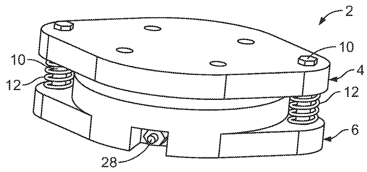
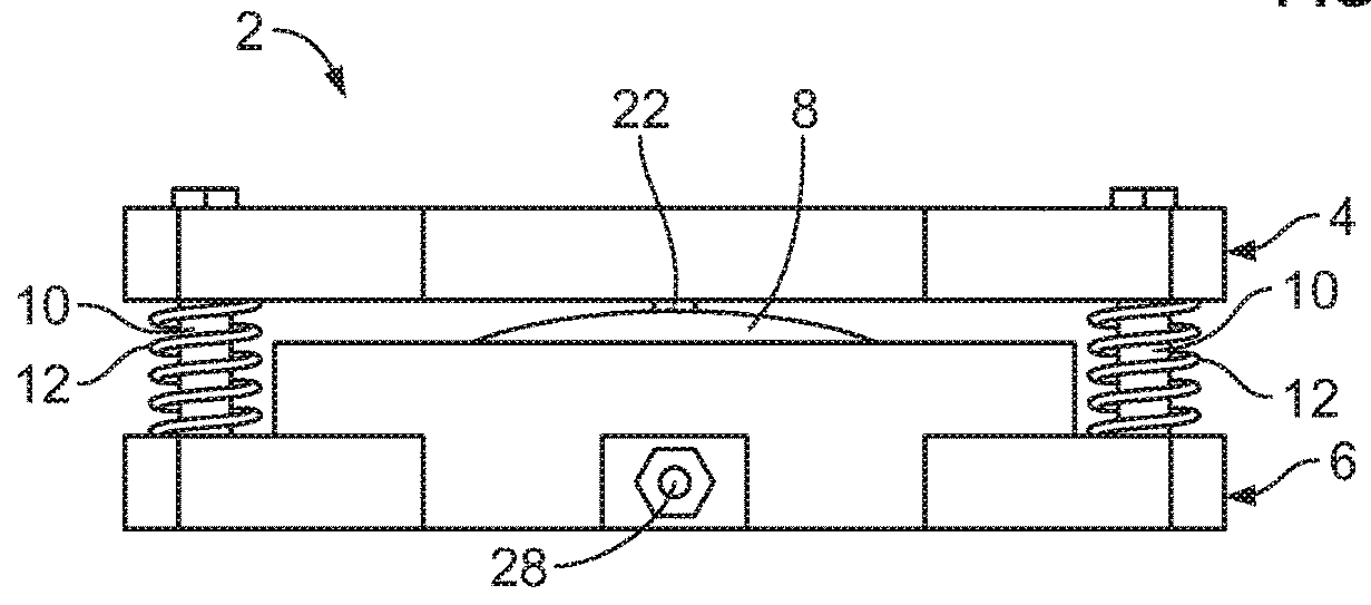
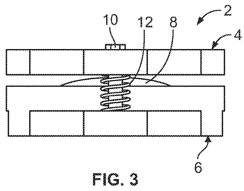
[0040]Referring generally to FIGS. 1-12, it will be appreciated that a vacuum pump system for use in suspension of a prosthetic device from a residual limb of the present disclosure generally may be embodied within numerous configurations of pump systems. For instance, this disclosure includes example pump systems for suspending a prosthetic device from a residual limb, such as shown in FIGS. 1-5 featuring an example mechanically activated pump, or as shown in FIGS. 6-10 featuring a hybrid pump system including a mechanically activated pump that is connected to an electrically activated pump, or as shown in FIGS. 11-12 featuring another hybrid pump system including a mechanically activated pump and an electrically activated pump that have an integrated housing.

[0041]As disclosed in U.S. patent application Ser. No. 13 / 529,833, it is common that a prosthetic device or limb may be provided for transfemoral or transtibial amputees. In a transfemoral configuration, such a prosthetic devi...


PUM


Abstract

Pump systems for use in suspension of a prosthetic device from a residual limb and methods of suspending a prosthetic device from a residual limb are disclosed. The pump systems include a mechanically activated pump having a first compression member coupled to a second compression member, a diaphragm disposed between the first and second compression members, and coupling elements that engage and couple together the first and second compression members. The mechanically activated pump may be connected with an electrically activated pump, forming a hybrid pump system to provide vacuum engagement between a prosthetic device and a residual limb.

Description

CROSS-REFERENCE TO RELATED APPLICATION[0001]This application claims the benefit of priority of U.S. Provisional Patent Application Ser. No. 62 / 214,560, filed Sep. 4, 2015 and PCT Application Serial No. PCT / US16 / 47775, filed Aug. 19, 2016, the disclosure of which is hereby incorporated by reference in its entirety.CONTRACTUAL ORIGIN OF THE INVENTION[0002]This invention was made with government support under W81XWH-10-1-0744 awarded by the U.S. Army Medical Research and Material Command. The government has certain rights in the invention.BACKGROUND OF THE INVENTIONField of the Invention[0003]The present invention generally relates to suspension systems for prosthetic devices, and more particularly to vacuum pump systems for prosthetic limbs that include at least a mechanically activated pump.Discussion of the Prior Art[0004]Various systems have been developed for coupling a prosthetic device or prosthetic limb to a residual limb. The residual limb is connected to the prosthesis via a ...

Claims


Application Information

Patent Timeline
Patent Type & Authority Applications(United States)
IPC IPC(8): A61F2/68A61F2/80A61F2/60
CPCA61F2/68A61F2/80A61F2/60A61F2002/802A61F2002/742A61F2/70A61F2002/807A61F2/742
Inventor CALDWELL, RYAN J.MAJOR, MATTHEW J.
Owner THE GOVERNMENT OF THE UNITED STATES OF AMERICA AS REPRESENTED BY THE DEPT OF VETERANS AFFAIRS
Why Eureka
Try Eureka