Blood recirculation device

Inactive Publication Date: 2018-09-27
CATHOLIC KWANDONG UNIV IND FOUND
View PDF3 Cites 0 Cited by
  • Summary
  • Abstract
  • Description
  • Claims
  • Application Information

AI Technical Summary

Benefits of technology

The present invention is a blood recirculation device that can efficiently recycle blood without damaging it during a suction procedure. It does not use a roller pump, reducing mechanical damage and the risk of complications. The device can also provide continuous suction and supply blood to an artificial heart-lung machine or a red blood cell cleaning system. It can effectively transfuse blood and can be easily adapted for use in various medical applications.

Problems solved by technology

This method is advantageous in that the total circulating blood volume can be maintained by immediately supplying the blood from bleeding to the artificial heart-lung machine, but is disadvantageous in that mechanical damage to blood by a roller pump is caused by using the roller pump as a unit for transferring the blood from bleeding.
However, the centrifugal pump does not work with a mixture including air, and therefore, the centrifugal pump is used mainly to circulate the blood in arterial and venous lines of the artificial heart-lung machine and the roller pump is used for the blood in other lines.
Here, the pressure on the tube results in damage to the blood in the tube, and the administration of the damaged blood may cause various complications.
On the other hand, blood from bleeding occurring during surgery needs to be promptly removed because the blood may interfere with the surgical field of vision, and therefore, the suction function needs to be continuously conducted.
In addition, in cases where the sucked blood is recirculated, the less the blood is damaged, the lower the risk of complications.
For the suction of blood without using a roller pump, negative pressure may be used, but the negative pressure is difficult to maintain while the collected blood is injected into the artificial heart-lung machine, and continuous suction cannot be used.

Method used


Image

  • Blood recirculation device
  • Blood recirculation device
  • Blood recirculation device

Examples


Embodiment Construction

Technical Problem

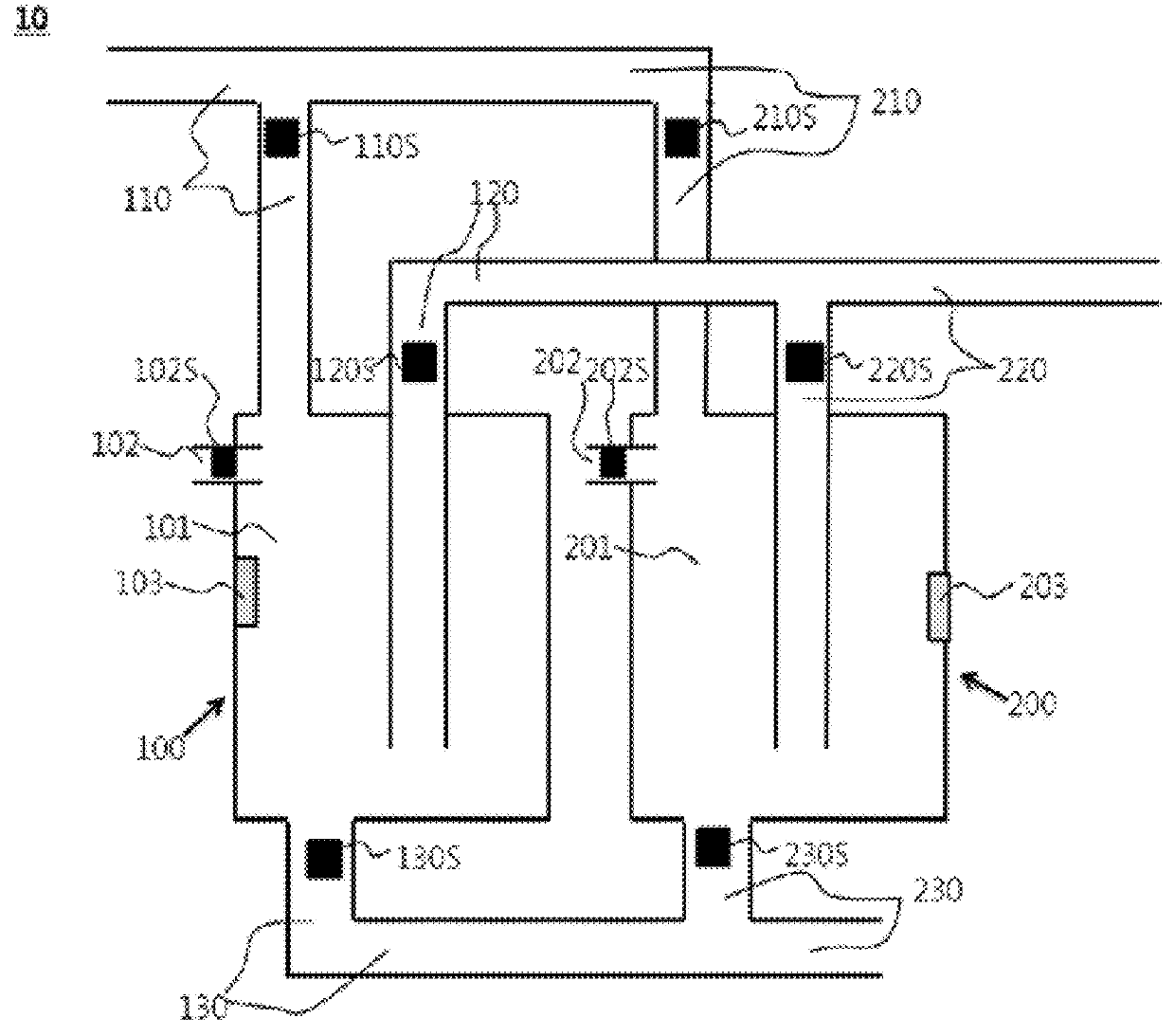
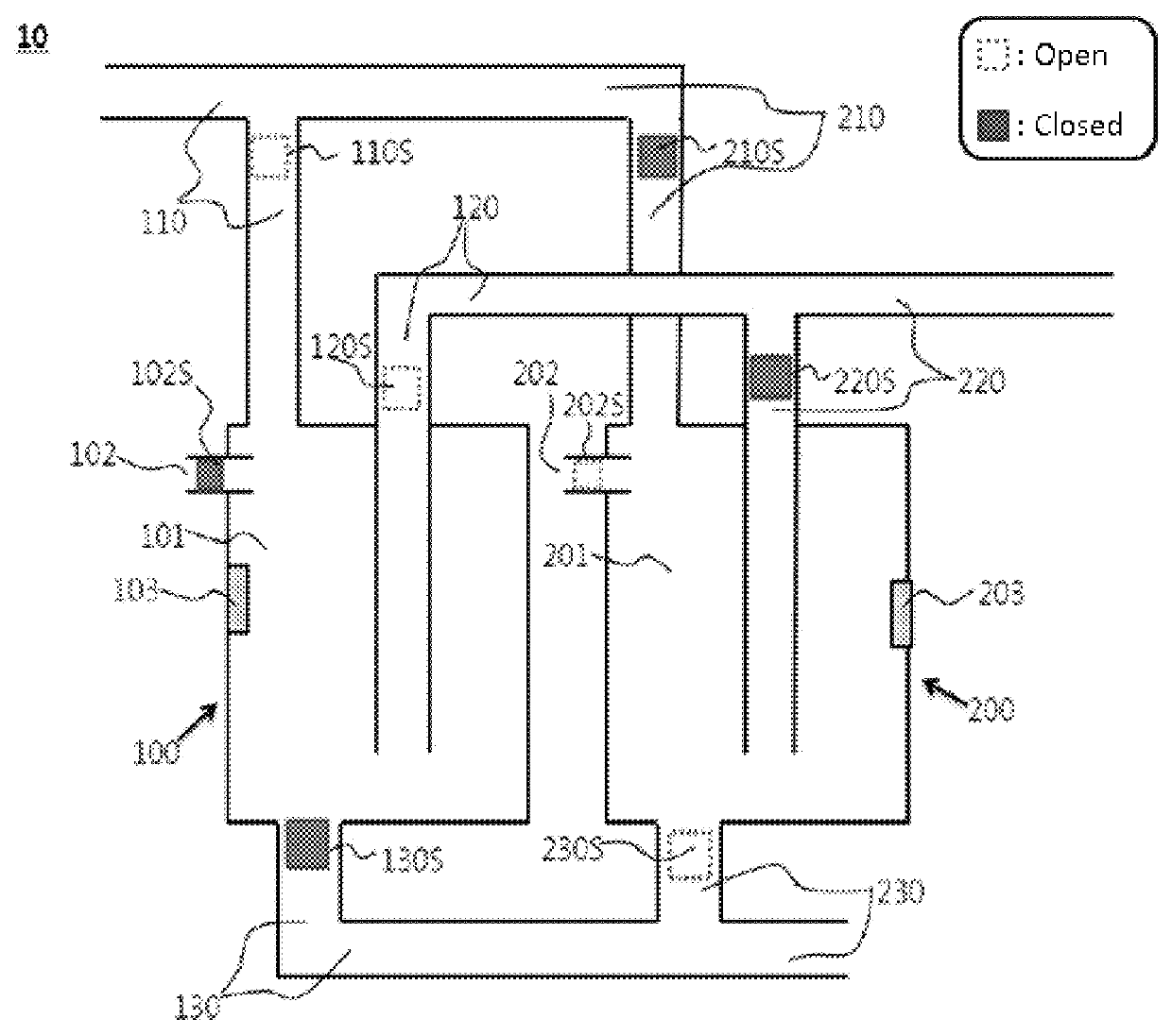
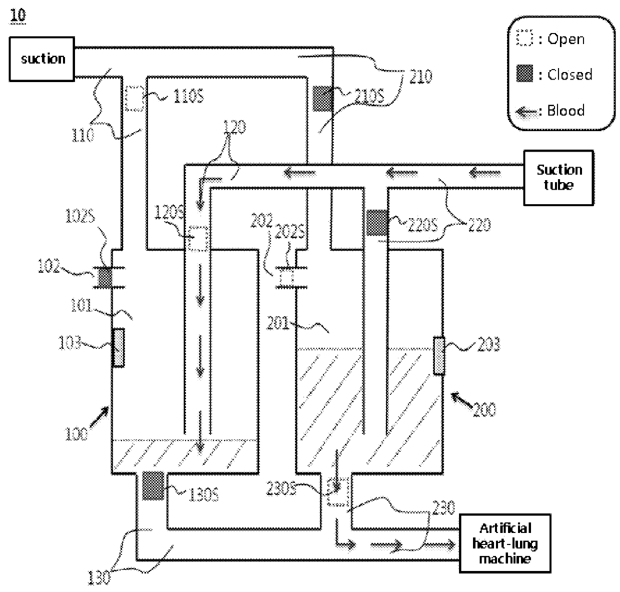
[0008]Under this background, the present inventors have endeavored to develop a device capable of achieving continuous suction while preventing mechanical damage to sucked blood during the use of a roller pump. As a result, the present inventors have developed a blood recirculation device wherein a plurality of device units, each of which sucks blood using negative pressure and then automatically transfers the blood to an artificial heart-lung machine when the volume of the sucked blood arrives at a certain level, are installed, so that while the blood stored in one device unit is transferred to the artificial heart-lung machine, the blood from bleeding can be sucked into another device unit, thereby achieving continuous suction and preventing mechanical damage to blood.

[0009]Accordingly, an aspect of the present invention is to provide a blood recirculation device.

[0010]Other purposes and advantages of the present invention will become more obvious with the followi...


PUM


Abstract

The present invention relates to a blood recirculation device. More particularly, the present invention relates to a blood recirculation device capable of continuous blood suction and capable of minimizing mechanical damage to the blood during such a process. The blood recirculation device according to the present invention repeats suction with one side unit and repeats a process of transferring stored blood with the other side unit, thereby being capable of continuous blood suction and capable of efficiently supplying suctioned blood to an erythrocyte washing system of an autologous blood transfusion machine or a cardiopulmonary bypass machine.

Description

TECHNICAL FIELD[0001]The present invention relates to a blood recirculation device. More specifically, the present invention relates to a blood recirculation device capable of achieving continuous suction of blood and minimizing mechanical damage to blood during such a procedure.BACKGROUND ART[0002]For the reuse of blood from bleeding occurring during surgery, there is a method in which the blood from bleeding is sucked using a roller pump, stored in a reserve chamber of an artificial heart-lung machine for a short time, and then again supplied to a venous line of the artificial heart-lung machine, in the case of surgery using heparin, such as heart surgery.[0003]This method is advantageous in that the total circulating blood volume can be maintained by immediately supplying the blood from bleeding to the artificial heart-lung machine, but is disadvantageous in that mechanical damage to blood by a roller pump is caused by using the roller pump as a unit for transferring the blood fr...

Claims


Application Information

Patent Timeline
IPC IPC(8): A61M1/00A61M1/02A61M1/36
CPCA61M1/0007A61M1/0259A61M1/3666A61M1/0023A61M1/0094A61M2205/3331A61M2205/3389A61M2205/3393A61M2205/07A61M2202/0413A61M1/0281A61M1/3627A61M2202/0429A61M1/3692A61M1/631A61M1/73A61M1/88
Inventor YOON, CHEESOON
Owner CATHOLIC KWANDONG UNIV IND FOUND
Why Eureka
Try Eureka