Check patentability & draft patents in minutes with Patsnap Eureka AI!

Method for operating a motor vehicle, control unit and motor vehicle

Inactive Publication Date: 2018-10-04
ROBERT BOSCH GMBH
View PDF4 Cites 3 Cited by
  • Summary
  • Abstract
  • Description
  • Claims
  • Application Information

AI Technical Summary

Benefits of technology

The present invention provides a method for controlling the individual wheels of a vehicle in a way that prevents spinning of one of the wheels and ensures rapid intervention in the operating behavior of the vehicle. The method takes into account factors such as the vehicle speed, wheel loads, and steering angle to determine the desired speed for each wheel. By controlling the speed of each wheel, the method prevents spinning of one of the wheels and ensures safe driving conditions. Additionally, the method takes into account the vehicle speed as a function of external factors such as the vehicle speed, acceleration, and yaw rate to have a more accurate measure of the vehicle speed.

Problems solved by technology

However, if the driver input is greater than the motive force transmittable to the ground or the roadway, then one or more of the driven wheels of the motor vehicle may spin and lose adhesion to the roadway.
Such a loss of traction may occur primarily in response to uneven ground and subsurfaces having different coefficients of friction, and may result in damage to sensitive ground surfaces.
In the case of individual-wheel drive having automatic speed control, exceedance of the adhesion limit of the driven wheels may result in all of the wheels being able to spin simultaneously and the motor vehicle consequently being able to become unstable.
In particular, power output is limited (automatically or manually) as a function of the current roadway composition, in order to prevent a loss of adhesion, that is, the spinning of all of the driven wheels.
However, since, in a controlled system, the accuracy of the control is a function of the measured parameters, and these are limited due to the desired simplicity of the system, then, for example, without speed determination independent of the vehicle and without determination of wheel loads, the controlled operation is preferably implemented only on sensitive roadways, on which the spinning of the driven wheels is supposed to be prevented, and / or only at low speeds, in particular, less than the above-mentioned limiting value.

Method used


Image

  • Method for operating a motor vehicle, control unit and motor vehicle
  • Method for operating a motor vehicle, control unit and motor vehicle

Examples


Embodiment Construction

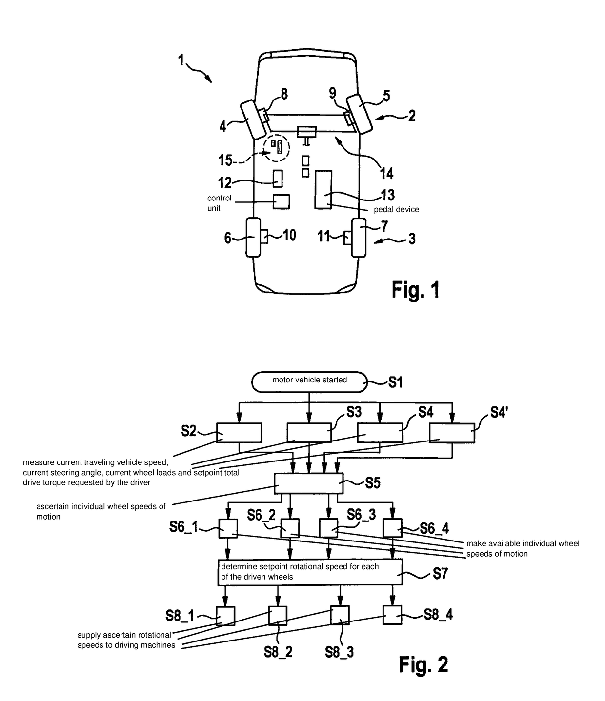
[0018]FIG. 1 shows a simplified top view of a motor vehicle 1, which includes a front wheel axle 2 and a rear wheel axle 3. The two wheel axles 2, 3 each include two driven wheels 4, 5 and 6, 7, respectively. In this context, each of driven wheels 4 through 7 is assigned a driving machine 8, 9, 10, 11, which, in each instance, takes the form of an electrical machine. In this context, driving machines 8 through 11 take the form of driving machines close to the rim, in particular, wheel-hub driving machines, which may transmit, directly or via a transmission gear, a positive or negative drive torque to associated driven wheels 4 through 7, respectively. To control driving machines 8 through 11, a control unit 12, which is connected to driving machines 8 through 11 via signals, is provided. In addition, driving machines 8 through 11 are each connected to an electrical energy store 13 by power electronics of control unit 12, the electrical energy store providing driving machines 8 throu...


PUM


Abstract

A method for operating a motor vehicle, which includes driven wheels and driving machines, each driven wheel being assigned a driving machine, respectively, the method including determining a setpoint total drive torque; measuring a current vehicle traveling speed, a current steering angle and, optionally, the wheel loads of all of the driven wheels; determining individual wheel speeds of motion of the driven wheels over the roadway as a function of the current vehicle traveling speed, the current steering angle, a chassis geometry of the motor vehicle and, optionally, the wheel loads; determining a setpoint rotational speed for each driven wheel as a function of the determined speeds of motion, and distributing the setpoint total drive torque to all driven wheels so that spinning of the specific driven wheel on the roadway is prevented; and controlling each driving machine to set the setpoint rotational speed at the specific driven wheel.

Description

CROSS REFERENCE[0001]The present application claims the benefit under 35 U.S.C. § 119 of German Patent Application No. DE 102017205473.5 filed on Mar. 31, 2017, which is expressly incorporated herein by reference in its entirety.[0002]The present invention relates to a method for operating a motor vehicle, which includes a plurality of driven wheels and a plurality of driving machines, each driven wheel being assigned a driving machine, in particular, an electrical machine.[0003]In addition, the present invention relates to a control unit for operating a motor vehicle, as well as to a motor vehicle and such a control unit, the control unit implementing the above-mentioned method.BACKGROUND INFORMATION[0004]With the increasing electrification of motor vehicles, the electrification of the power train also increases. Besides an internal combustion engine, one or more electrical machines may additionally be provided as driving machines. As an alternative to the internal combustion engin...

Claims


Application Information

Patent Timeline
IPC IPC(8): B60L3/10B60K7/00
CPCB60L3/102B60L3/106B60K7/0007B60L2240/12B60L2240/24B60L2240/22B60L2240/14B60L2240/423B60L2240/461B60L2240/463B60L2240/421B60K7/00B60K28/16B60K17/356Y02T10/64
Inventor NORDMANN, MARTIN
Owner ROBERT BOSCH GMBH
Features
  • R&D
  • Intellectual Property
  • Life Sciences
  • Materials
  • Tech Scout
  • Unparalleled Data Quality
  • Higher Quality Content
  • 60% Fewer Hallucinations
Learn More