Reinforcing structure for a wind turbine blade

a technology of reinforcing structure and wind turbine blade, which is applied in the direction of motors, applications, domestic articles, etc., can solve the problems of difficult to arrange the various structural layers in the mould in conformance with the mould surface, unusable parts, and wrinkles in the corners of the mould, so as to reduce the factory footprint of the manufacturing process, reduce the manufacturing process footprint, and maintain the effect of cross section

Active Publication Date: 2018-10-04
VESTAS WIND SYST AS
View PDF7 Cites 20 Cited by
  • Summary
  • Abstract
  • Description
  • Claims
  • Application Information

AI Technical Summary

Benefits of technology

[0023]A particular advantage of the present invention is that it requires significantly fewer process steps than the prior art. In particular, once the reinforcing structure is removed from the mould, the process is substantially complete and no further process steps are necessary. This is in sharp contrast to the prior art, which requires the additional process steps of bonding return flanges and trimming the edges of the moulded component to allow for safe handling. In the present invention, the edges of the reinforcing structure may be defined by edges of the flange structures, which may conveniently already be safe for handling. The present invention also reduces the factory footprint of the manufacturing process since there is no requirement for additional processing stations for bonding and trimming, for example.
[0024]In preferred embodiments of the invention, the flange structure has a substantially constant cross section along its length. This facilitates the layup process and stock control since a single design of flange structure may be used along the entire length of the reinforcing structure.
[0025]In particularly preferred embodiments, the flange structure is a pultruded component. This is advantageous because pultruded components are relatively cheap. They also have smooth edges and hence ensure that the edges of the reinforcing structure can be handled safely immediately upon removal from the mould. Pultruded components can also be manufactured easily to a required length or cut to a required length. The pultrusion process used to form the flange structure may involve drawing bundles of loose fibres and / or fibres in the form of tapes through a pultrusion die.
[0026]The flange structure is preferably substantially T-shaped in cross-section. This shape is easy to form by pultrusion. Alternatively, the flange structure could have any suitable shape. For example it may be L-shaped in cross-section. The flange structure may be a single element that extends along substantially the entire length of the reinforcing structure, or alternatively a plurality of flange structures may be arranged in series along the length of the reinforcing structure.
[0027]In certain embodiments the flange portion may be in the form of a substantially flat strip. In some embodiments described in detail later, the flange portion is wedge-shaped. The flange portion may have a V-shaped or curved outer surface. The projecting portion may form an angle of approximately 90 degrees (e.g. 90 degrees+ / −a few degrees) with an inner surface of the flange portion. The flange portion may advantageously have a substantially flat inner surface from which the projecting portion projects.
[0028]The present invention allows reinforcing structures of varying height to be formed by making simple adjustments to the mould apparatus.

Problems solved by technology

This is because the sidewalls of the C-shaped mould make it difficult to arrange the various structural layers in the mould in conformance with the mould surface.
In particular there is a tendency for wrinkles to develop in the materials in the corners of the mould between the base of the mould and the sidewalls.
Any wrinkles or other inaccuracies in the layup can lead to weaknesses in the moulded panel 64, which could render the part unusable.
The C-shaped mould tool used to form the shear web 14 is also relatively expensive.
It is therefore prohibitive in terms of cost to vary the design of the shear web 14 from one blade to another to accommodate variations in the blade design such as to accommodate the varying shell thicknesses employed in high and low wind class blade designs.
However, adhesive is expensive and adds significantly to the weight of the blade and hence the current solution is not necessarily optimal.
This process is time consuming and adds cost to the manufacturing process.
Bonding of the L-shaped return flanges 66a, 66b to the C-shaped panel 64 is also time-consuming and adds further cost and complexity to the process.

Method used


Image

  • Reinforcing structure for a wind turbine blade
  • Reinforcing structure for a wind turbine blade
  • Reinforcing structure for a wind turbine blade

Examples


Embodiment Construction

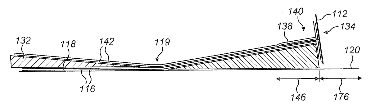
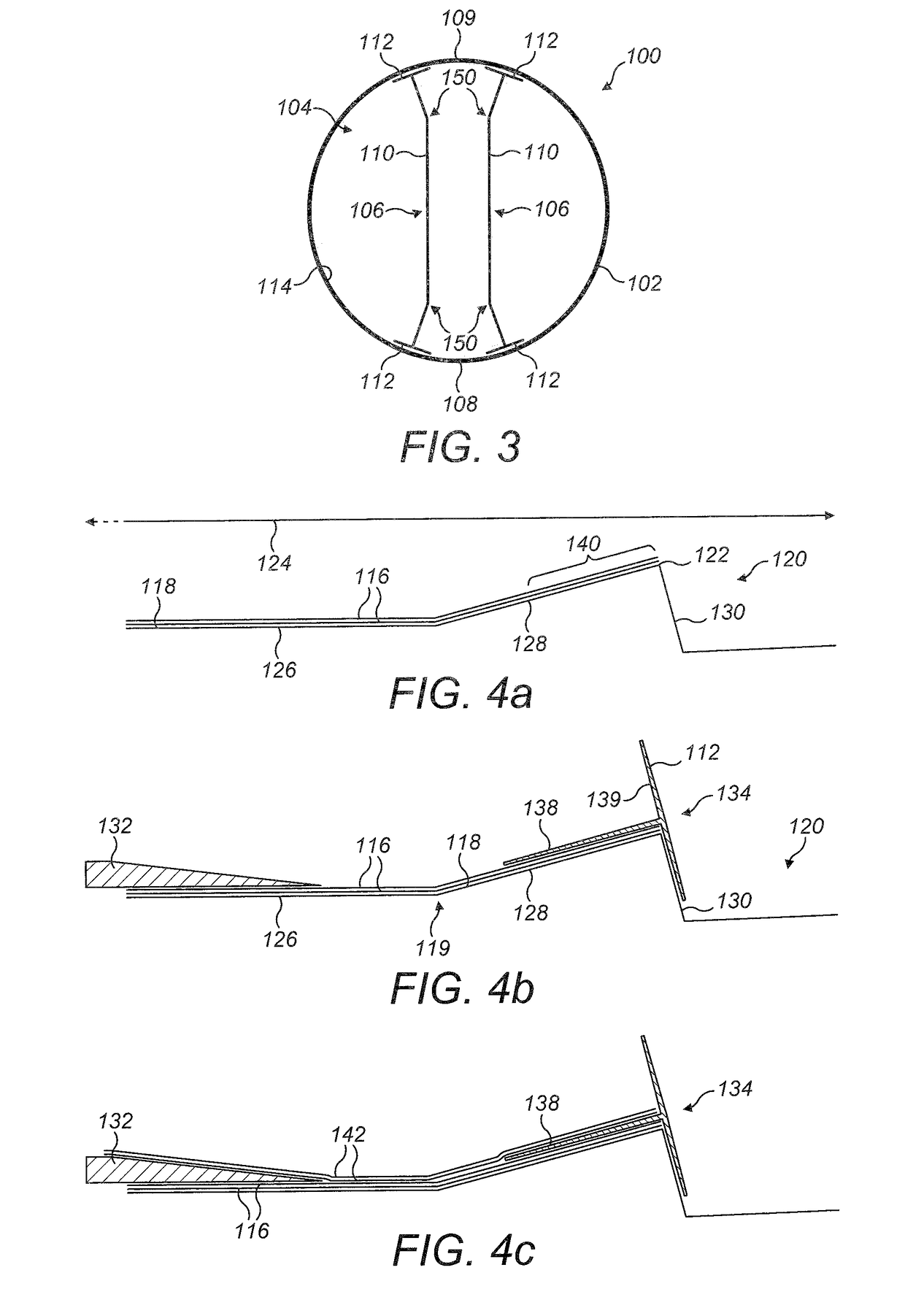
[0060]Referring to FIG. 3, this shows a schematic cross-section through a circular root end of a wind turbine blade 100. The blade comprises an outer shell 102 defining a substantially hollow interior 104. A pair of shear webs 106 according to the present invention extend longitudinally inside the blade 100, perpendicular to the plane of the page, and are connected between windward and leeward sides 108, 109 of the blade shell 102.

[0061]The shear webs 106 include a web portion 110 having flanges 112 at each end. The web portion 110 is kinked to accommodate the high degree of curvature at the root end of the blade 100. This allows the flanges 112 of the shear webs 106 to be arranged flush with an inner surface 114 of the blade shell 102 whilst an intermediate section of the web portion 110 extends substantially vertically, in the orientation of the blade 100 shown in FIG. 3.

[0062]As will be readily apparent to persons skilled in the art, the profile of the wind turbine blade 100 vari...


PUM

PropertyMeasurementUnit
angleaaaaaaaaaa
lengthaaaaaaaaaa
heightaaaaaaaaaa

Abstract

A method of making an elongate reinforcing structure, such as a shear web, for a wind turbine blade is described. The reinforcing structure comprises a longitudinally-extending web and a longitudinally-extending flange. The flange extends along a longitudinal edge of the web and is arranged transversely to the web. The method involves providing a flange structure comprising a flange portion, and a projecting portion that extends along the length of the flange portion and projects transversely from a surface of the flange portion. The projecting portion is bonded between laminate layers of the web. The flange structure is preferably a pultruded component having a T-shaped cross-section. The method allows a simple, inexpensive and reconfigurable mould tool to be used. In preferred embodiments the mould tool has a flat surface without sidewalls.

Description

TECHNICAL FIELD[0001]The present invention relates to a reinforcing structure for a wind turbine blade and to a method of making a reinforcing structure.BACKGROUND[0002]Modern wind turbine blades typically comprise an outer shell of composite construction. The outer shell may be formed from a windward half shell and a leeward half shell bonded together, or alternatively the outer shell may be formed as a single moulding.[0003]One or more load-bearing structures such as spars are typically located inside the blade. A known spar structure is shown schematically in FIG. 1, which is a transverse cross-section through part of a wind turbine blade 10. Referring to FIG. 1, this shows a spar structure 12 comprising a shear web 14 and a pair of spar caps 16a, 16b. The spar caps 16a, 16b are embedded in the outer shell 18 of the wind turbine blade 10. The spar caps 16a, 16b are arranged in opposed relation and are located respectively in windward and leeward sides 20a, 20b of the outer shell ...

Claims


Application Information

Patent Timeline
Patent Type & Authority Applications(United States)
IPC IPC(8): F03D1/06B29D99/00
CPCF03D1/0675B29D99/0028B29D99/0003F05B2240/30F05B2280/6003B29K2063/00B29K2105/089F03D80/00B29L2031/085Y02P70/50Y02E10/72
Inventor WARDROPPER, STEVESMITH, JONATHANHEDGES, ANDREWRANDALL, STEPHEN
Owner VESTAS WIND SYST AS
Why Eureka
Try Eureka