Plasma transfer wire arc thermal spray system

A plasma and transfer arc technology, applied in the direction of plasma, injection device, liquid injection device, etc., can solve the problems of high machine and operation cost, undesigned, etc., and achieve the effects of prolonged nozzle life, easy start-up and high efficiency

Active Publication Date: 2012-03-07
FORD GLOBAL TECH LLC
View PDF4 Cites 7 Cited by
  • Summary
  • Abstract
  • Description
  • Claims
  • Application Information

AI Technical Summary

Problems solved by technology

Additional air supply results in higher machine and operating costs
Also, the system was not designed to be modified to direct the arc starting flame moment

Method used


Image

  • Plasma transfer wire arc thermal spray system
  • Plasma transfer wire arc thermal spray system
  • Plasma transfer wire arc thermal spray system

Examples


Embodiment Construction

[0057] Hereinafter, the present invention will be described in detail with reference to the accompanying drawings.

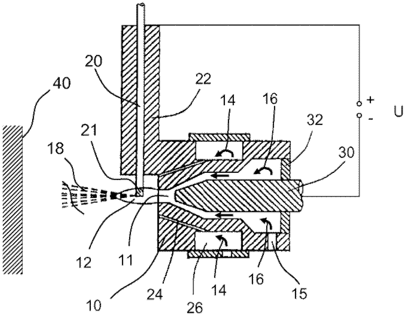
[0058] Reference will now be made in detail to presently preferred combinations or embodiments and methods of the invention, which constitute the best modes of carrying out the invention currently known to the inventors. In one embodiment of the present invention, an improved PTWA spray gun is provided. The spray gun of the present invention is a component in a plasma wire transferred arc thermal spray apparatus that can be used to spray a surface with a dense metallic coating. The torch of the present invention comprises a wire feed guide having a wire feed guide for supplying wire into the plasma flame, an auxiliary gas portion for providing auxiliary gas surrounding the plasma formed by the plasma flame, and Assembly of the nozzle portion of the formed plasma.

[0059] refer to figure 1 , shows a schematic of the thermal spray process. In thermal spraying...


PUM


Abstract

The invention relates to a plasma transfer wire arc thermal spray system, comprising a section for feeding a wire (20) acting as a first electrode, a source of plasma gas providing plasma gas (16), a nozzle (10) directing the plasma gas stream (16) from the source of plasma gas to a free end (21 ) of the wire (20), and a second electrode (30) located in the plasma gas stream (16) towards the nozzle. The inventions is characterized in that the nozzle (10) is made at least partially of electrically insulating material. The thermal spray apparatus with the inventive spray gun is having a simplified and faster starting procedure and is the spray nozzle is more durable.

Description

technical field [0001] The present invention relates generally to plasma transferred wire arc (PTWA) thermal spraying systems and methods of thermally spraying materials, and more particularly to thermal spraying apparatus with spray guns that are simple and quick to start. Background technique [0002] Thermal spraying provides a complete and economical technical solution for applying high-performance, wear-resistant coatings to less wear-resistant materials. Thermal spraying of metal particles produced by feeding powder or feeding wire is a common process for coating metal surfaces. This allows a base material with poorer properties for an application to be covered with a harder plasma-sprayed layer with other properties that are better for the application, and can be used to replace parts made entirely of materials with better properties . In this way, it is also possible to combine the preferred properties of the base material (eg light weight etc.) with the hardness o...

Claims


Application Information

Patent Timeline
Patent Type & Authority Applications(China)
IPC IPC(8): B05B7/22
CPCB05B7/06B05B7/224B05B13/0636C23C4/131H05H1/42
Inventor L·施拉姆A·施文克E·郝赛尔
Owner FORD GLOBAL TECH LLC
Why Eureka
Try Eureka