
Flue Assembly and Splash Back Panel for a Cooking Appliance

a technology for cooking appliances and splashbacks, which is applied in the field of flushing systems for cooking appliances, can solve the problems of grease “baking” and achieve the effect of preventing grease from “baking-on”

Active Publication Date: 2018-10-11
ALTO SHAAM
View PDF50 Cites 9 Cited by
  • Summary
  • Abstract
  • Description
  • Claims
  • Application Information

AI Technical Summary

Benefits of technology

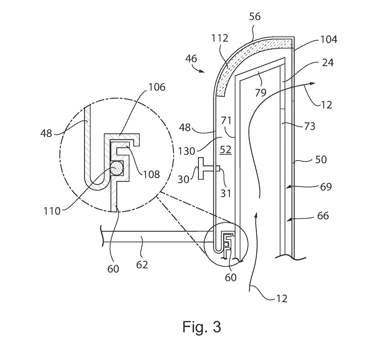
The present invention is a deep fryer with a flue and splash back panel separated by a separating panel. The flue opening is positioned at the rear of the fryer to prevent grease or debris from falling back into the flue. The splash back panel is designed to be seamless and easy to clean, and is insulated from the heat of the flue. A baffle is installed within the flue to reduce the temperature and heating of the splash back panel. The invention vents hot air through the back of the fryer to make cleaning easier, eliminates a top vent opening to prevent debris from falling into the flue, keeps the fryer cool, and reduces the exhaust gas temperature and velocity by mixing the air within the baffle. The splash-back panel remains cool and does not become "baked on" with grease.

Problems solved by technology

While splash-back panels are meant to collect grease on the back wall behind the fryer kettle, the present inventors have recognized that maintenance associated with keeping the splash back panel clean is made difficult by high temperatures of the flue, which cause grease to “bake on” to the back wall when the splash back panel is the flue.
Moreover, the upward flue opening exposes the flue to falling grease and other foreign objects, which may accidentally enter the flue.
This is particularly a problem with fryers that use atmospheric burners employing convection to transport the flue gases (as opposed to power burners having blowers for transporting flue gases) because the flue opening is relatively large in order to facilitate the natural convection of air.

Method used


Image

  • Flue Assembly and Splash Back Panel for a Cooking Appliance
  • Flue Assembly and Splash Back Panel for a Cooking Appliance
  • Flue Assembly and Splash Back Panel for a Cooking Appliance

Examples


Embodiment Construction

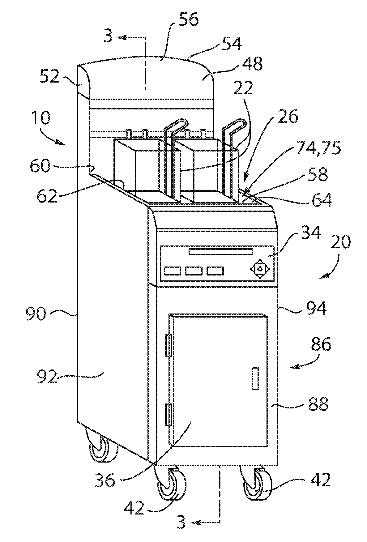
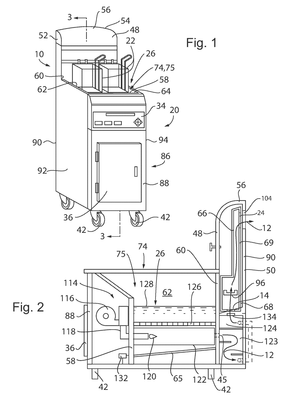
[0031]Referring to FIGS. 1-2, a flue system 10 of the present invention may work with a deep fat fryer 20 of the type typically found in commercial kitchens. The fryer 20 may provide an outer main housing having an outer covering 86 being generally a rectangular cuboid having an upstanding front wall 88 in parallel opposition to an upstanding rear wall 90 both connected at their left and right edges by upstanding left 92 and right 94 walls respectively.

[0032]The front wall 88 of the fryer 20 may provide an exterior control panel 34 having a digital display and various control buttons for selection of on / off, power level, temperature selection, cooking modes, etc. At the front wall 88 below the control panel 34 may be a door 36 enclosing an opening of the front wall 88 providing access to an interior of the outer covering 86, holding, for example, equipment or electronics. The outer covering 86 may be stainless steel to prevent corrosion and high temperature resistant to prevent defo...


PUM


Abstract

The present invention provides a deep fat fryer separating the flue from the splash back panel and with a flue opening directed not upwardly, but rearwardly from the flue. By arranging the flue opening on the rear wall, the opening is protected from grease fallback (e.g., dripping from an overhead exhaust hood) or other foreign objects falling into the opening. The splash back panel further provides a seamless curved design that is easy to clean and also insulated from the heat of the flue. A baffle installed within the flue allows the combustion products to mix, cool, and slow upon exiting the baffle opening and entering the atmosphere reducing the exit temperature and also reducing the heating of the splash back panel.

Description

CROSS REFERENCE TO RELATED APPLICATION[0001]This application claims the benefit of U.S. provisional application 62 / 482,909 filed Apr. 7, 2017 and hereby incorporated by reference.STATEMENT REGARDING FEDERALLY SPONSORED RESEARCH OR DEVELOPMENT[0002]--BACKGROUND OF THE INVENTION[0003]The present invention relates to a flue system for a cooking appliance using a gas burner such as a deep fat fryer, and in particular, to a flue assembly providing a splash-back panel of the cooking appliance and exhaust gases vented rearwardly.[0004]Deep fat fryers, such as those commercially available under the trademark FryTech™ from Alto-Shaam®, Inc., located in Menomonee Falls, Wis. provide oil kettles heated by burners that are exhausted or vented by a flue at the rear of the fryer. The flue allows for directed movement of combustion products through the flue and out through a flue opening. The flue opening is typically positioned within a chimney extending upward at the rear of the fryer kettle or ...

Claims


Application Information

Patent Timeline
IPC IPC(8): A47J37/12
CPCA47J37/1276F24C15/20A47J36/38
Inventor STOLLENWERK, THOMAS C.INSISIENGMAY, C. PHILIPBUFORD, JEREMY J.MCMAHON, GEORGE
Owner ALTO SHAAM
Learn More