Chain guide mechanism

a guide mechanism and chain technology, applied in the direction of belts/chains/gearrings, machines/engines, machines/engines, etc., can solve the problems of poor work efficiency during assembly or maintenance, and achieve the effects of reducing overall production costs, and improving work efficiency during assembly and maintenan

Active Publication Date: 2018-10-11
TSUBAKIMOTO CHAIN CO +1
View PDF0 Cites 4 Cited by
  • Summary
  • Abstract
  • Description
  • Claims
  • Application Information

AI Technical Summary

Benefits of technology

[0013]That the coupling member is formed separately as an independent component allows the coupling member to be of a material or have properties specifically selected to achieve ideal clearance setting in consideration of heat shrinkage, or to achieve ideal component strength or deformation resistance or the like when the pivoting chain guide rocks, without affecting the characteristics required for other constituent elements, and therefore the overall production cost can be reduced.
[0014]According to the configuration set forth in claim 2, the arm members each include a sprocket holding part that makes sliding contact with a sprocket. Thus the sprocket can reliably be integrated.
[0015]According to the configuration set forth in claim 3, the connecting arms are joined together by a fixing wall provided on an opposite side to the engaging portion across the fitting hole. The connecting arms are therefore in a U-shaped clip form and hardly open outward near the fitting hole, so that the pivoting chain guide is prevented from coming off.
[0016]According to the configuration set forth in claim 4, the locking portions of the arm members and the engaging portions of the connecting arms of the coupling member are formed such that the connecting arms engage with the arm members from inside of the arm members. Therefore, when the coupling member is engaged with the arm members, the connecting arms of the coupling member can hardly open, so that the mounting boss of the pivoting chain guide is prevented from coming off from the fitting hole.
[0017]According to the configuration set forth in claim 5, the arm members are formed integrally with a guide shoe that constitutes the chain running surface of the fixed chain guide. The connection unit and fixed chain guide can be united only by attaching the guide shoe of the fixed chain guide to a fixed guide support member, and thus the work efficiency during assembly and maintenance can be improved.
[0018]According to the configuration set forth in claim 6, the locking portion of each of the arm members includes a rocking movement slot for allowing the coupling member to rock around the fitting hole. Thus the pivoting chain guide and coupling member can be pivoted together after assembly. This allows the mounting boss of the pivoting chain guide to be secured to the fitting hole instead of being loosely fitted therewith. As the two components are firmly joined together, the work efficiency during assembly and maintenance can be improved.

Problems solved by technology

One problem with this chain guide mechanism was poor work efficiency during assembly or maintenance since the pivoting chain guide 520 is pivotally mounted in the engine room (not shown) with a mounting shaft B while the fixed chain guide 530 is fixed to the engine room with mounting shafts B1 and B2, which means that the drive sprocket S1, driven sprockets S2 and S3, pivoting chain guide 520, and fixed chain guide 530 had to be individually assembled or disassembled, and the chain C had to be separately passed over the sprockets or removed therefrom.

Method used


Image

  • Chain guide mechanism
  • Chain guide mechanism
  • Chain guide mechanism

Examples


embodiment 1

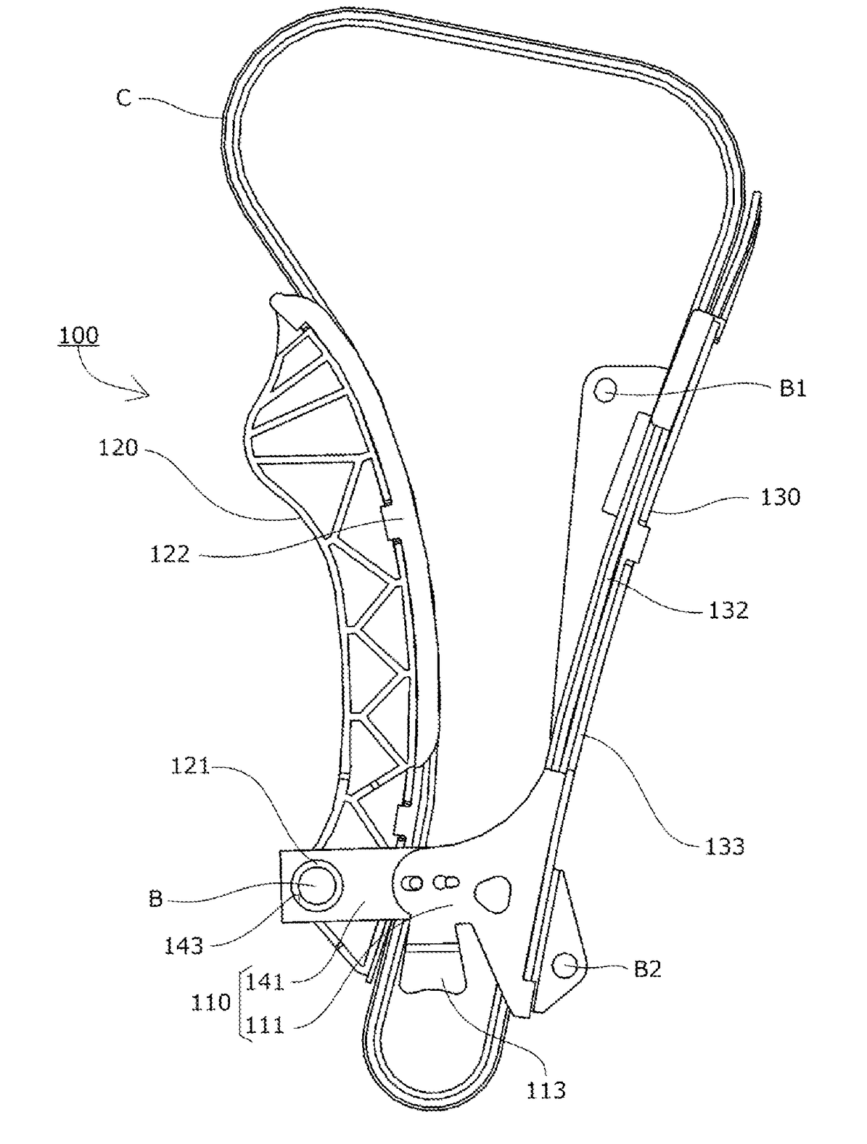
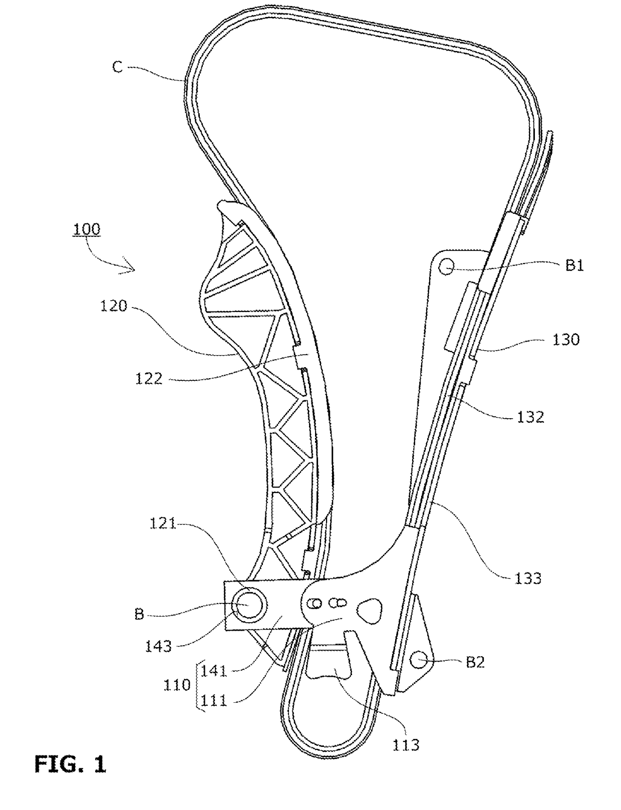
[0034]A chain guide mechanism 100 that is a first embodiment of the present invention includes, as shown in FIG. 1 to FIG. 4, a fixed chain guide 130 that slidably guides a chain C, a pivoting chain guide 120 that slidably guides the chain C, and a connection unit 110 that connects the fixed chain guide 130 and the pivoting chain guide 120.

[0035]The pivoting chain guide 120 includes cylindrical mounting bosses 121.

[0036]The connection unit 110 is made up of a pair of arm members 111 that extend from both sides of the chain C on the chain running surface of the fixed chain guide 130 toward the pivoting chain guide 120, and a coupling member 141 including fitting holes 143 for the mounting bosses 121 of the pivoting chain guide 120 to fit in.

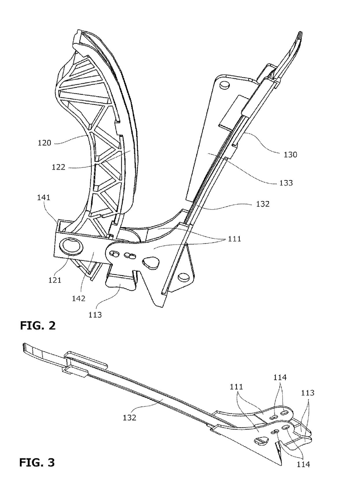
[0037]The arm members 111 are integrally formed with a guide shoe 132 that forms the chain running surface of the fixed chain guide 130, and each include a sprocket holding part 113 that makes sliding contact with a sprocket (not shown).

[0038]The ...

embodiment 2

[0047]The chain guide mechanism that is a second embodiment of the present invention is configured basically the same as that of the first embodiment described above apart from the designs of the mounting bosses 121 of the pivoting chain guide 120, fitting holes 143 of the coupling member 141, and locking portions of the arm members 111.

[0048]The mounting boss 121 of the pivoting chain guide 120 in the second embodiment includes an anti-rotation tab 123 extending radially outward as shown in FIG. 5 for fitting into an anti-rotation slot 146 provided on the radially outer side of the mounting boss 121 of the pivoting chain guide 120.

[0049]The locking holes 114 that form the locking portions of the arm members 111 are provided with rocking movement slots 114a for allowing the coupling member 141 to rock around the mounting shaft B that is the pivot center of the pivoting chain guide 120.

[0050]In the first embodiment, the mounting bosses 121 have to be loosely fitted into the fitting h...


PUM


Abstract

To provide a chain guide mechanism that enables a plurality of chain guides, a chain, and a sprocket to be held together with a simple structure, such that work efficiency during assembly and maintenance is improved. The chain guide mechanism joins a plurality of chain guides that slidably guide a chain; and a connection unit is made up of arm members that extend from both sides of the chain on a chain running surface of a fixed chain guide toward a pivoting chain guide, and a coupling member including a fitting hole for a mounting boss of the pivoting chain guide to fit in.

Description

BACKGROUND OF THE INVENTION1. Field of the Invention[0001]The present invention relates to made up of a fixed guide that slidably guides a chain, a pivoting lever guide that slidably guides the chain, and a connection unit that connects the fixed guide and the pivoting lever guide, specifically to a chain guide mechanism that is suited, for example, to an engine timing system where chain guides maintain the tension of, and slidably guide, an endless chain such as a silent chain or roller chain passed over sprockets respectively provided to a crankshaft and cam shafts inside an engine room.2. Description of the Related Art[0002]In conventionally known engine timing systems, an endless chain C is passed over a drive sprocket S1 and a pair of driven sprockets S2 and S3 respectively attached to a crank shaft and cam shafts inside an engine room as shown in FIG. 8. A chain guide mechanism is configured with a pivoting chain guide 520 that guides the chain while maintaining appropriate te...

Claims


Application Information

Patent Timeline
Patent Type & Authority Applications(United States)
IPC IPC(8): F16H7/18F16H7/08
CPCF16H7/18F16H7/08F16H2007/0872F16H2007/087F16H2007/0874F16H2007/185F02B67/06
Inventor MAEDA, MUNEHIROBELMER, STEFANHAFDALLAOUI, MEHER
Owner TSUBAKIMOTO CHAIN CO
Why Eureka
Try Eureka