High Precision Trajectory and Speed Sensor and Measuring Method

a speed sensor and high-precision technology, applied in the field of timing systems, can solve the problems of inability to obtain precise timing information from video analysis, time-consuming current analysis procedure, and inability to provide information, and achieve the effect of causing a large time loss

Inactive Publication Date: 2018-10-11
ECOLE POLYTECHNIQUE FEDERALE DE LAUSANNE (EPFL)
View PDF0 Cites 8 Cited by
  • Summary
  • Abstract
  • Description
  • Claims
  • Application Information

AI Technical Summary

Benefits of technology

[0014]In a preferred embodiment the magnetic strength of a permanent magnet is increased by aligning at least two smaller permanent magnets spaced apart by iron yokes or a non-magnetic spacing material such as plastic or wood.
[0019]In a preferred embodiment, the method further comprises improving a precision of the skiing trajectory estimated with the GNSS system, thereby estimating a magnet position of each passed permanent magnet, comparing the estimated magnet positions with the true magnet positions, obtaining an initial trajectory estimation error for each magnet, from a result of the comparing, and interpolating between each estimation error and subtraction of an error curve from the initial trajectory estimation, thereby obtaining the precision improved skiing trajectory estimation.

Problems solved by technology

Although video feedback is crucial, the current analysis procedure is time consuming and provides no information with respect to instantaneous skiing speed, for example.
Moreover, video analysis provides only limited possibilities for obtaining precise timing information, for example for gate-to-gate timing.
For example, a speed loss due to a small error may not be relevant immediately when the error happened but the effect may induce a large time loss only after a few gates.
In another example, the effect of choosing two different skiing trajectories may result in a large time difference only after a few gates.
Thus, the speed and trajectory of the athlete's CoM cannot be measured directly.
Especially the athlete's pendular movements during the turns may result in large speed and trajectory differences between the speed and trajectory measured with the GNSS antenna and the athlete's true CoM speed and trajectory.
Another major drawback of the differential GNSS is its complex setup: additional fixed ground stations are required, gate positions need to be surveyed, and the instrumentation is rather heavy, often requiring wearing a backpack.
Such a system fails to meet the requirements of easy handling and uncomplicated use needed for a training application.

Method used


Image

  • High Precision Trajectory and Speed Sensor and Measuring Method
  • High Precision Trajectory and Speed Sensor and Measuring Method
  • High Precision Trajectory and Speed Sensor and Measuring Method

Examples


Embodiment Construction

[0058]A typical example of the invention will now be described by referencing the figures.

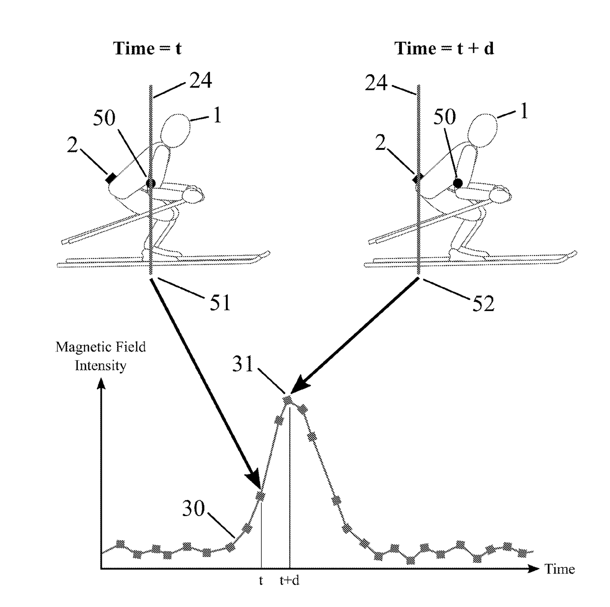
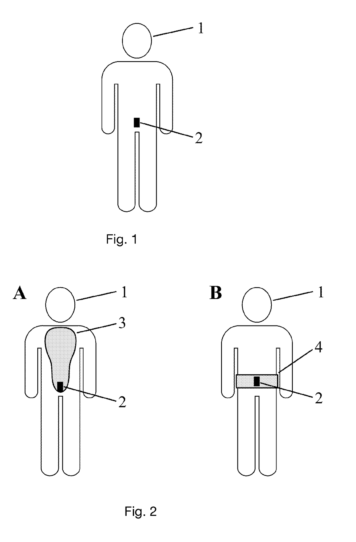
[0059]Referring to FIG. 1, in a preferred embodiment of the invention a magnetometer sensor unit 2 is attached to the athlete 1 using adhesive tape. The magnetometer sensor unit 2 is attached closely to the sacrum of the athlete 1, on his lower back.

[0060]Referring to FIG. 2A, in another preferred embodiment of the invention the magnetometer sensor unit 2 is integrated in a back protector 3, for example a standard protector complying to the rules of the Federation Internationale de Ski (F.I.S.). Referring to FIG. 2B, in another preferred embodiment of the invention the magnetometer sensor unit 2 is integrated into a kidney belt 4.

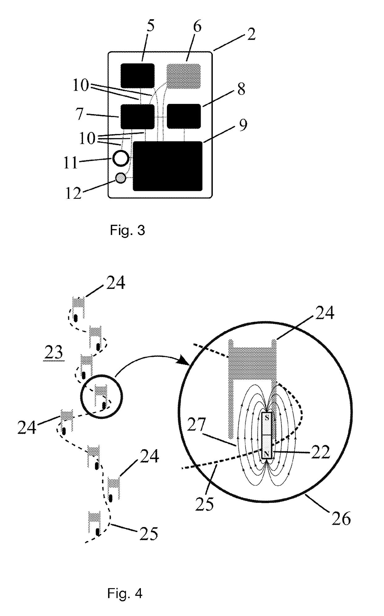
[0061]Referring to FIG. 3, this illustrates an example embodiment of the magnetometer sensor unit 2 comprising of a high performance 3D magnetic sensor 5 capable of sampling at least at 50 Hz. In an example embodiment this may be for example a Melexis MLX90393 sampling...


PUM


Abstract

A method for contactlessly determining an exact passage of an athlete at points placed along a track in sports, wherein the method comprises gearing the athlete with a wearable magnetometer sensor unit, whereby the magnetometer sensor unit is equipped with at least a magnetic sensor, a processing unit, and a storage medium; placing at each point at least a permanent magnet in proximity of a track surface of the track. When the athlete moves along the track, the method further comprises recording at the magnetic sensor a signal; detecting for each permanent magnet a disturbance of a local magnetic field generated by the permanent magnet in the recorded signal and measuring the disturbance; mapping of the measured disturbance to a movement speed of the athlete and a distance of the athlete to the magnet corresponding to the local magnetic field; and correcting the movement speed and the distance for a time offset between the magnet passage of an athlete's center of mass and the magnetometer sensor unit.

Description

TECHNICAL FIELD[0001]The present invention relates to a timing system, and in a preferred embodiment also to a timing and motion tracking system. More particularly the invention's timing and / or tracking system is for use in alpine ski racing.BACKGROUND[0002]In alpine ski racing performance is measured as the time from start to finish of a run. In order to provide useful feedback to athletes, coaches usually analyze key sections of the run.[0003]Currently, standard video analysis is used as the main mean of feedback to the athletes. Using dedicated video analysis software (e.g., Dartfish, Switzerland), different runs can be manually synchronized and compared to each other. Although video feedback is crucial, the current analysis procedure is time consuming and provides no information with respect to instantaneous skiing speed, for example. Moreover, video analysis provides only limited possibilities for obtaining precise timing information, for example for gate-to-gate timing.[0004]A...

Claims


Application Information

Patent Timeline
Patent Type & Authority Applications(United States)
IPC IPC(8): G01P3/50A63B69/18A63B71/06A63B71/12G01P15/18G01P15/16G01P15/14
CPCG01P3/50A63B69/18A63B71/0616A63B71/12G01P15/18G01P15/165G01P15/14A63B2225/50A63B2071/0691A63B2209/08A63B2220/12A63B2220/36A63B2220/34A63B2220/44A63B2220/836A63B2244/19A63B24/0084A63B2220/30G01P3/00
Inventor FASEL, BENEDIKTAMINIAN, KAMIAR
Owner ECOLE POLYTECHNIQUE FEDERALE DE LAUSANNE (EPFL)
Why Eureka
Try Eureka