Drive device and drive system

a technology of a drive device and a drive system, which is applied in the direction of dynamo-electric converter control, propulsion by batteries/cells, transportation and packaging, etc., can solve the problems of electromagnetic sound noise and large noise due to electromagnetic sound, so as to reduce noise, maintain predetermined controllability, and curb the deterioration of the controllability of the motor

Inactive Publication Date: 2018-10-11
TOYOTA JIDOSHA KK
View PDF6 Cites 2 Cited by
  • Summary
  • Abstract
  • Description
  • Claims
  • Application Information

AI Technical Summary

Benefits of technology

[0005]A drive device and a drive system according to the disclosure reduce noise due to electromagnetic sound.
[0008]In the drive device according to the disclosure, the first PWM control of generating a first PWM signal for the plurality of switching elements by comparison of modulated waves of voltage commands in phases based on a torque command for the motor with a carrier voltage and performing switching of the plurality of switching elements and the second PWM control of generating a second PWM signal for the plurality of switching elements based on a modulation factor of a voltage and a voltage phase based on the torque command and the number of pulses per unit period of an electrical angle of the motor and performing switching of the plurality of switching elements are selectively performed. Switching to the first PWM control and the second PWM control is performed at irregular time intervals. By switching the switching elements between the first PWM control and the second PWM control, times at which the plurality of switching elements are turned on and off can be changed, and contained current harmonics (a frequency (an order) having a large content by percentage in current harmonics) can be changed (diffused) at the irregular time intervals. Accordingly, by switching the switching elements between the first PWM control and the second PWM control at irregular time intervals, it is possible to change (diffuse) the contained current harmonics at the irregular time intervals. As a result, it is possible to reduce noise due to electromagnetic sound.
[0009]The first PWM control may be synchronous pulse width modulation control, and the electronic control unit may be configured to set a synchronization number of the carrier voltage in the first PWM control and the number of pulses in the second PWM control to the same value. Accordingly, since a predetermined number of pulses can be maintained at the time of switching between the first PWM control and the second PWM control by setting the synchronization number and the number of pulses to the same value, it is possible to maintain predetermined controllability. The electronic control unit may be configured to set the number of pulses such that a total loss of the motor and the inverter when the second PWM control is performed is minimized.
[0010]The first PWM control may be synchronous pulse width modulation control, and the electronic control unit may be configured to: switch the plurality of switching elements from the first PWM control to the second PWM control at a time of a zero-crossing of one of the modulated waves of the voltage commands of the phases that are used to generate the first PWM signal for the plurality of switching elements; and switch the plurality of switching elements from the second PWM control to the first PWM control at a time of a zero-crossing time of one of modulated waves of virtual voltage commands of the phases corresponding to the second PWM signal for the plurality of switching elements. According to this configuration, it is possible to curb deterioration of controllability of the motor at the time of switching between the first PWM control and the second PWM control.

Problems solved by technology

In the drive device, change of contained current harmonics (a frequency (an order) having a large content by percentage in current harmonics) may be small and noise due to electromagnetic sound may become large.
Particularly, when an electric motor is driven normally (when the number of pulses, the modulation factor, and the voltage phase are substantially constant), noise due to electromagnetic sound is likely to become large.

Method used


Image

  • Drive device and drive system
  • Drive device and drive system
  • Drive device and drive system

Examples


Embodiment Construction

[0020]Hereinafter, an embodiment of the disclosure will be described with reference to the accompanying drawings.

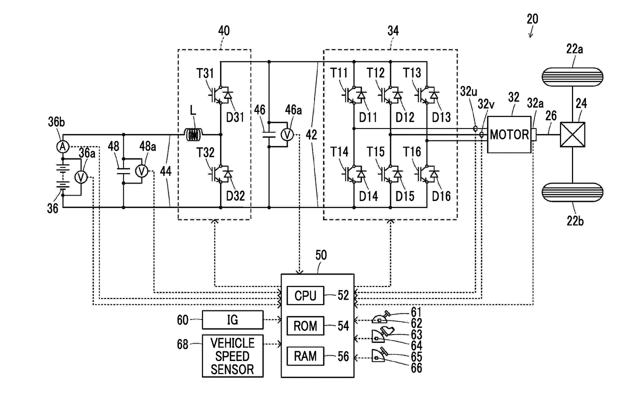
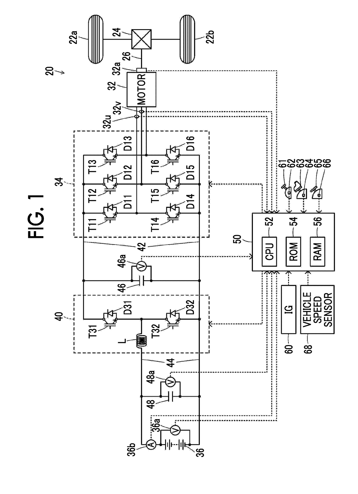
[0021]FIG. 1 is a diagram schematically illustrating a configuration of an electric vehicle 20 in which a drive device according to an embodiment of the disclosure is mounted. As illustrated in the drawing, the electric vehicle 20 according to the embodiment includes a motor 32, an inverter 34, a battery 36 serving as a power storage device, a boost converter 40, and an electronic control unit 50.

[0022]The motor 32 is configured as a synchronous generator motor and includes a rotor that has a permanent magnet embedded therein and a stator on which three-phase coils are wound. The rotor of the motor 32 is connected to a drive shaft 26 connected to driving wheels 22a and 22b via a differential gear 24.

[0023]The inverter 34 is used to drive the motor 32. The inverter 34 is connected to the boost converter 40 via power lines 42 on a high voltage side and includes six transist...


PUM


Abstract

First pulse width modulation control is a control of generating a first pulse width modulation signal for a plurality of switching elements by comparison of modulated waves of voltage commands in phases based on a torque command for a motor with a carrier voltage, and performing switching of the plurality of switching elements. Second pulse width modulation control is a control of generating a second pulse width modulation signal for the plurality of switching elements based on a modulation factor of a voltage and a voltage phase based on the torque command and the number of pulses per unit period of an electrical angle of the motor, and performing switching of the plurality of switching elements. An electronic control unit is configured to switch the plurality of switching elements between the first pulse width modulation control and the second pulse width modulation control at irregular time intervals.

Description

INCORPORATION BY REFERENCE[0001]The disclosure of Japanese Patent Application No. 2017-077312 filed on Apr. 10, 2017 including the specification, drawings and abstract is incorporated herein by reference in its entirety.BACKGROUND1. Technical Field[0002]The disclosure relates to a drive device and a drive system, and more particularly to a drive device and a drive system that include a motor and an inverter.2. Description of Related Art[0003]In the related art, a type of drive device which includes an electric motor and a power conversion device having an inverter circuit that drives the electric motor by switching a plurality of switching elements and which generates pulse signals of the plurality of switching elements based on the number of pulses in one electrical period of the electric motor and a modulation factor of a voltage and a voltage phase based on a torque command for the electric motor to switch the plurality of switching elements has been proposed (for example, see Ja...

Claims


Application Information

Patent Timeline
Patent Type & Authority Applications(United States)
IPC IPC(8): H02P27/08H02P6/08H02M1/12H02M7/5395B60L11/18
CPCH02P27/085H02P6/08H02M1/12H02M7/5395B60L11/1803B60L2210/40H02P29/50H02M1/44B60L50/51H02P2201/07B60L15/08B60L2210/14B60L2240/429B60L2270/142Y02T10/64Y02T10/72Y02T10/70H02M1/007
Inventor YAMAMOTO, TOSHIHIROYAMADA, KENJI
Owner TOYOTA JIDOSHA KK
Why Eureka
Try Eureka