Deep groove ball bearing with a rotor

a technology of deep groove ball bearings and rotors, which is applied in the direction of connecting rod bearings, bearing unit rigid supports, mechanical instruments, etc., can solve the problems of difficult realization of the current bearing manufacturing, and achieve the effects of good sealing performance, long service life and small siz

Active Publication Date: 2018-10-18
NINGBO ZHENHAI SILVER BALL BEARING CO LTD
View PDF0 Cites 2 Cited by
  • Summary
  • Abstract
  • Description
  • Claims
  • Application Information

AI Technical Summary

Benefits of technology

[0003]In view of the above-mentioned problems in the prior art, a deep groove ball bearing with a rotor that is capable of running smoothly under high revolution speed conditions is provided. The deep groove ball bearing has a small size, good sealing performance and long service life.
[0018]the mandrel provided with the groove cooperates with the outer ring to form the deep groove ball bearing structure, and the permanent magnet, with the balance ring at one end thereof, is integrated on the mandrel, and the O-rings are provided at the periphery of the outer ring, so that the bearing runs smoothly under high revolution speed conditions, and has a small size, good sealing performance and long service life; O-rings are installed on the outer ring to facilitate the damping and assemble and disassemble; the outer edge of the outer ring of the bearing is provided with the slot for glue storage to facilitate glue injection as needed after the installation of the bearing, so as to facilitate axial positioning of the bearing.

Problems solved by technology

The bearings used in micro-miniature motors require not only to be small in size, but also to run smoothly under high revolution speed conditions, which is difficult to realize for the current bearing manufacturing.

Method used


Image

  • Deep groove ball bearing with a rotor
  • Deep groove ball bearing with a rotor
  • Deep groove ball bearing with a rotor

Examples


embodiments 1

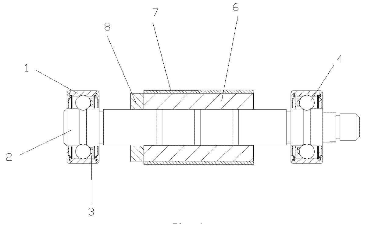
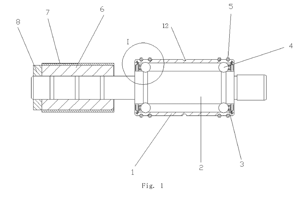
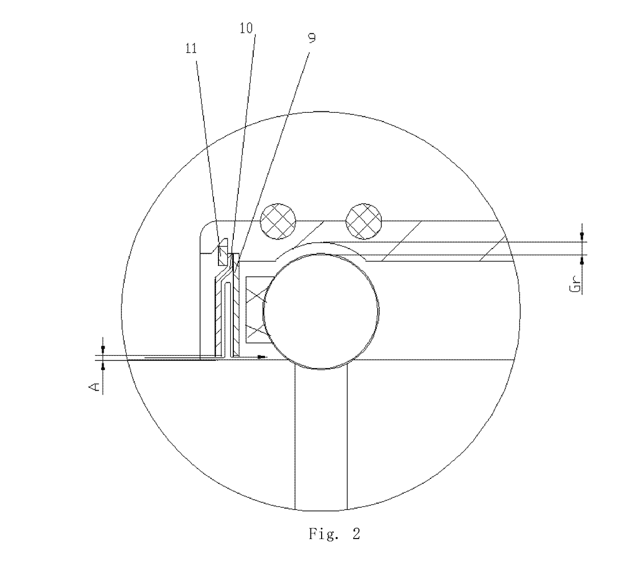
[0024]FIG. 1 is a structural schematic diagram of a first embodiment of the deep groove ball bearing with a rotor, and FIG. 2 is a partial enlarged view of part I in FIG. 1. As shown in FIGS. 1 and 2, the deep groove ball bearing with a rotor presented by the present invention comprises a mandrel 2, at least one bearing assembly structure mounted on a periphery of the mandrel 2, and a magnet structure, wherein the bearing assembly structure, along with the mandrel 2 to constitute the deep groove ball bearing structure, includes an outer ring 1 sleeved on the periphery of the mandrel 2, steel balls 4, and an inner sealing cover 9; wherein the periphery of the mandrel 2 is provided with at least one lap of channel 13 that matches with a groove provided on an inner surface of the outer ring 1, and the steel balls 4 are installed between the channel 13 and the groove; wherein an end opening of the out ring 1 is axially embedded with an inner sealing cover 9 for sealing an inner side of ...

embodiments 2

[0034]Referring to FIG. 3, a structural schematic diagram of a second embodiment of the deep groove ball bearing with a rotor is shown. The structure and content of the deep groove ball bearing with a motor presented by this embodiment are substantially the same as those of the above-described embodiment 1, except that in the present embodiment, the balance ring 8 is provided on the side of the permanent magnet 6 adjacent to the outer ring 1, and the mandrel 2 is in a straight-through configuration.

embodiments 3

[0035]Referring to FIG. 4, a structural schematic diagram of a third embodiment of the deep groove ball bearing with a rotor is shown. The structure and content of the deep groove ball bearing with a motor presented by this embodiment are substantially the same as those of the above-described embodiment 1, except that in the present embodiment, there are two bearing assembly structures and one magnet structure, wherein the two bearing assembly structures are provided on the mandrel 2 on either side of the magnet structure, respectively. And the inner side of the outer ring 1 of each bearing assembly structure is respectively provided with one groove. In specific implementation, the permanent magnet, reinforcing sleeve and balance ring can be first stuck onto the mandrel and the outer rings on both ends are then assembled with the reinforcing sleeve and balance ring as needed.


PUM


Abstract

A deep groove ball bearing with a rotor is disclosed by the present invention. The deep groove ball bearing with a rotor comprises a mandrel, at least one bearing assembly structure mounted on the periphery of the mandrel, and a magnet structure; wherein the bearing assembly structure, along with the mandrel to constitute the deep groove ball bearing structure, includes an outer ring sleeved on the periphery of the mandrel, steel balls, and an inner sealing cover; wherein the periphery of the mandrel is provided with at least one lap of channel that matches with a groove provided on the inner surface of the outer ring, and the steel balls are installed between the channel and the groove; wherein the periphery of the out ring is axially embedded with an inner sealing cover for sealing the inner side of the outer ring; wherein the magnet structure includes a permanent magnet glued on the periphery of the mandrel, a reinforcing sleeve sleeved outside the permanent magnet, and a balance ring provided at one end of the permanent magnet. The technical solution enables the bearing to run smoothly under high revolution speed conditions, and has a small size, good sealing performance and long service life. O-rings are installed on the outer ring to facilitate the damping and assemble and disassemble.

Description

TECHNICAL FIELD[0001]The present invention relates to the field of bearings for micro-miniature precision motors, and particularly to a deep groove ball bearing with a rotor.BACKGROUND[0002]The motors available in micro-miniature motors market have a development tendency towards DC utilization, energy saving, miniaturization and high-speed rotation. Users require the motors to be small in size and high efficiency, with motor power to be generally 100˜600 W, revolution speed to be between 8 and 25 million revolutions per minute. The bearings used in micro-miniature motors require not only to be small in size, but also to run smoothly under high revolution speed conditions, which is difficult to realize for the current bearing manufacturing.SUMMARY OF THE INVENTION[0003]In view of the above-mentioned problems in the prior art, a deep groove ball bearing with a rotor that is capable of running smoothly under high revolution speed conditions is provided. The deep groove ball bearing has...

Claims


Application Information

Patent Timeline
Patent Type & Authority Applications(United States)
IPC IPC(8): F16C35/04F16C9/04F16C19/20F16C33/78
CPCF16C35/042F16C9/04F16C19/20F16C33/78F16C33/80F16J15/3444F16C25/086F16C33/583F16C33/7869F16C2380/26F16C33/782F16C33/7846F16C19/08F16C2240/76
Inventor LI, ZHIGENXIAO, HUAHAI
Owner NINGBO ZHENHAI SILVER BALL BEARING CO LTD
Why Eureka
Try Eureka