
Vehicle power-supply unit

a power supply unit and vehicle technology, applied in secondary cell servicing/maintenance, battery/fuel cell control arrangement, batteries, etc., can solve the problems of not being able to appropriately perform the charge stop processing using electric power of the low-voltage battery, and the low-voltage battery may continue to fall. , to achieve the effect of suppressing power loss, increasing convenience, and increasing power loss

Active Publication Date: 2018-11-01
HONDA MOTOR CO LTD
View PDF11 Cites 4 Cited by
  • Summary
  • Abstract
  • Description
  • Claims
  • Application Information

AI Technical Summary

Benefits of technology

The present invention relates to a power-supply unit for electronic devices that can stop external charging when there is a defect in the device being charged. The power-supply unit includes a lock mechanism to prevent unintended removal of the charging connector. The power-supply unit also includes a power converter that can supply electric power to the device being charged through another power line, even if there is an anomaly in the power converter. The technical effects of the invention include improved safety and convenience during external charging, as well as improved efficiency and reliability of the power-supply unit.

Problems solved by technology

In a low-voltage battery or during external charging, if an anomaly occurs in a power converter or the like for reducing the voltage of electric power supplied from an external power supply source and supplying it to the low-voltage battery, the voltage of the low-voltage battery may continue to fall even if the fail-safe processing of Japanese Patent Application Publication No. 2010-239670 is performed.
However, as mentioned earlier, if an anomaly occurs in the low-voltage battery or its power converter or the like, and the voltage of the low-voltage battery continues to fall while performing external charging, it may no longer be able to appropriately perform the charge stop processing using electric power of the low-voltage battery.

Method used


Image

  • Vehicle power-supply unit
  • Vehicle power-supply unit
  • Vehicle power-supply unit

Examples


Embodiment Construction

[0026]Hereinafter, an embodiment of the present invention will be described with reference to the drawings.

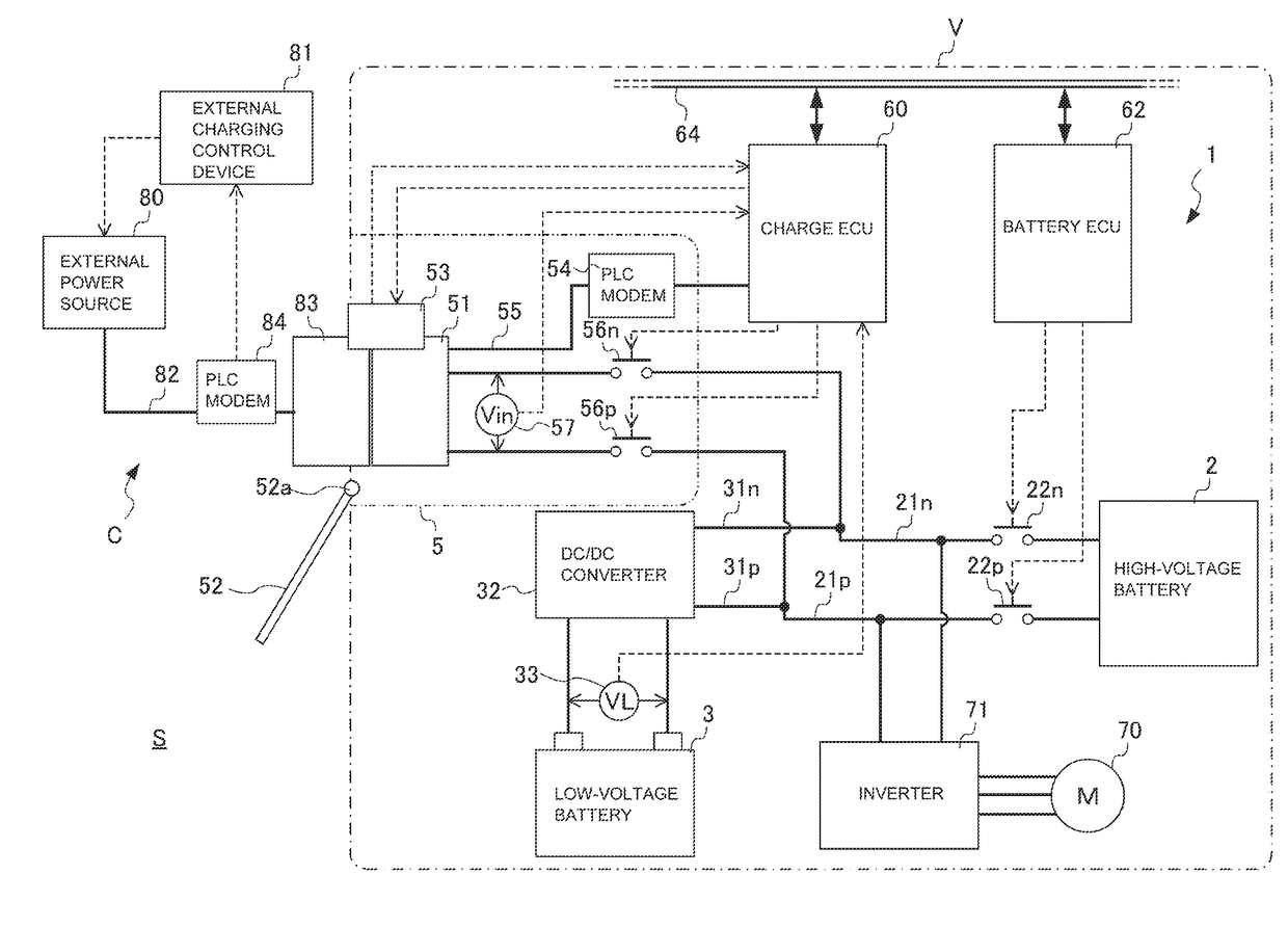
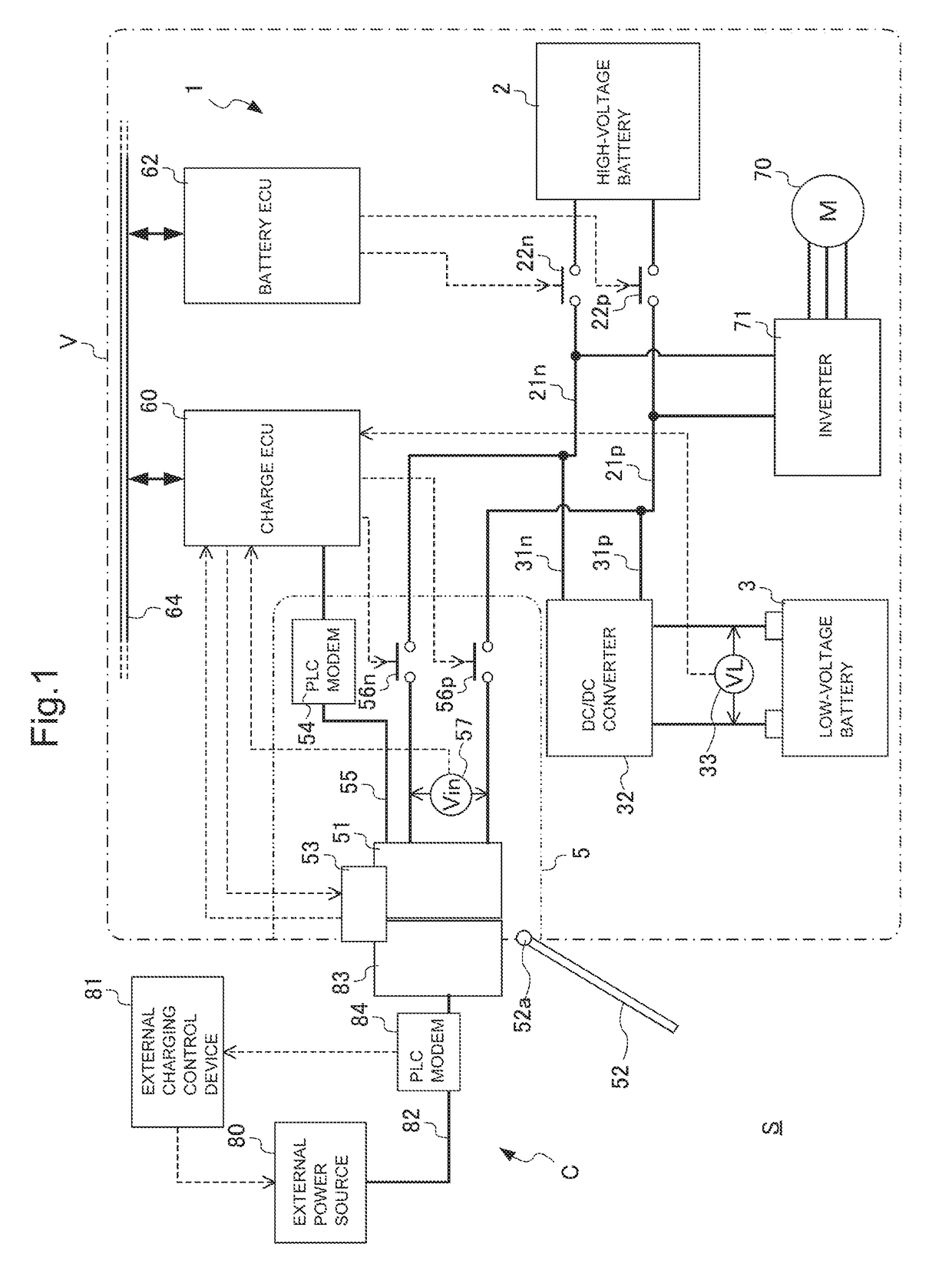
[0027]FIG. 1 is a diagram illustrating a configuration of an electric vehicle V (hereinafter simply referred to as “vehicle V”) including a power-supply unit 1 of the embodiment, and its charging system S. The charging system S is configured by combining the vehicle V with an external charger C.

[0028]The external charger C includes an external power source 80 that outputs direct current, an external charging control device 81 that controls output of the external power source 80, a feed connector 83 that is connected to the external power source 80 through a power line 82, and a PLC modem 84 for performing PLC communication which is communication via the power line 82.

[0029]The external charging control device 81 performs PLC communication, through the PLC modem 84, with a later-mentioned charge ECU 60 mounted on the vehicle V, and controls output of the power source 80 based on...


PUM

PropertyMeasurementUnit
voltageaaaaaaaaaa
electric poweraaaaaaaaaa
poweraaaaaaaaaa

Abstract

A vehicle power-supply unit includes a high-voltage battery, a low-voltage battery having a lower voltage than the high-voltage battery, and an inlet, and is capable of connecting a feed connector of an external power source to the inlet and supplying electric power from the external power source to a charge target which is at least one of the high-voltage battery and the low-voltage battery. The power-supply unit includes: charge control means that controls charging of the charge target; and a battery voltage sensor that detects a voltage of the low-voltage battery. If a low-voltage battery voltage value VL becomes not higher than a charge abort threshold Vabort while connecting the feed connector to the inlet and supplying electric power from the external power source to the charge target, the charge control means stops supply of electric power from the external power source to the charge target.

Description

CROSS-REFERENCE OF RELATED APPLICATION[0001]This application claims priority of Japanese Patent Application No. 2017-090547 filed in Japan on Apr. 28, 2017, the entire contents of which are incorporated herein by reference.TECHNICAL FIELD[0002]The present invention relates to a vehicle power-supply unit. More specifically, the invention relates to a vehicle power-supply unit that can supply electric power to at least one of two electric storage devices as a charge target, from an external power supply source.BACKGROUND OF THE INVENTION[0003]An electric vehicle that travels by use of electric power stored in a battery often includes two types of batteries, which are a high-voltage battery for mainly supplying electric power to a driving motor and air-conditioning equipment, for example, and a low-voltage battery for supplying electric power to so-called accessories such as lights, a navigation system, and an electronic control unit. These batteries are charged by an on-board generato...

Claims


Application Information

Patent Timeline
Patent Type & Authority Applications(United States)
IPC IPC(8): B60L11/18B60L3/00H01M10/44H02J7/00
CPCB60L11/1861B60L11/1809B60L3/0046H01M10/44H02J7/007B60L2210/10B60L2240/547H02J7/007182H01M10/48B60L58/12H01M2220/20B60L58/20H02J7/342B60L53/00B60L58/18Y02T10/72Y02T10/70Y02T10/7072Y02T90/14Y02E60/10H02J7/00
Inventor TSUTSUMI, DAISUKE
Owner HONDA MOTOR CO LTD
Learn More