Methods and systems for operating a redox flow battery system

battery system technology, applied in the direction of reactant parameter control, regenerative fuel cells, fuel cells, etc., can solve the problems of poor ion selectivity, lower overall efficiency of a redox flow battery, high resistivity and higher cost, etc., to achieve higher ion selectivity, reduce performance losses, and improve the effect of efficiency

Active Publication Date: 2018-11-01
ESS TECHNOLOGY
View PDF2 Cites 9 Cited by
  • Summary
  • Abstract
  • Description
  • Claims
  • Application Information

AI Technical Summary

Benefits of technology

[0004]Redox flow batteries are suitable for grid scale storage applications due to their capabilities of scaling power and capacity independently, and charging and discharging for thousands of cycles with reduced performance losses as compared with conventional battery technologies. Redox flow battery cells generally employ two different types of membrane separators: ion exchange membranes (IEMs) and microporous membranes. IEMs generally exhibit higher ion selectivity but higher resistivity and higher cost, while microporous membranes are less expensive and exhibit lower resistivities but are associated with poor ion selectivity. Operating with separators having low ion selectivities can lower overall efficiency of a redox flow battery.

Problems solved by technology

IEMs generally exhibit higher ion selectivity but higher resistivity and higher cost, while microporous membranes are less expensive and exhibit lower resistivities but are associated with poor ion selectivity.
Operating with separators having low ion selectivities can lower overall efficiency of a redox flow battery.
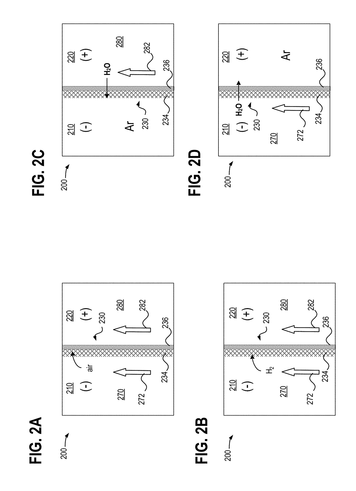
Namely, due to the hydrophobicity of the microporous membrane layer, the microporous membrane can be difficult to thoroughly wet with the aqueous electrolyte, and can become infiltrated with air and other gas bubbles diffusing therein.
The presence of gas bubbles in the microporous membrane layer can cause substantial increases in resistivity of the redox flow cell battery, which lowers battery efficiency.

Method used


Image

  • Methods and systems for operating a redox flow battery system
  • Methods and systems for operating a redox flow battery system
  • Methods and systems for operating a redox flow battery system

Examples


Embodiment Construction

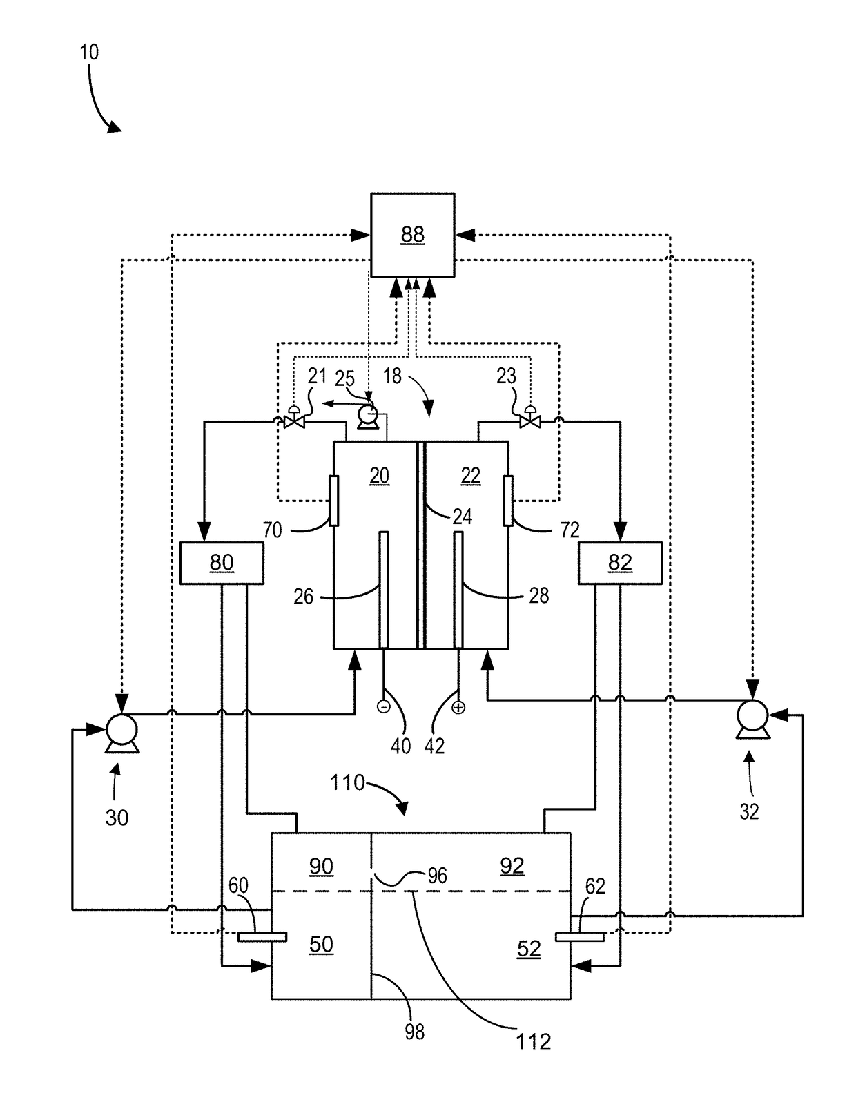
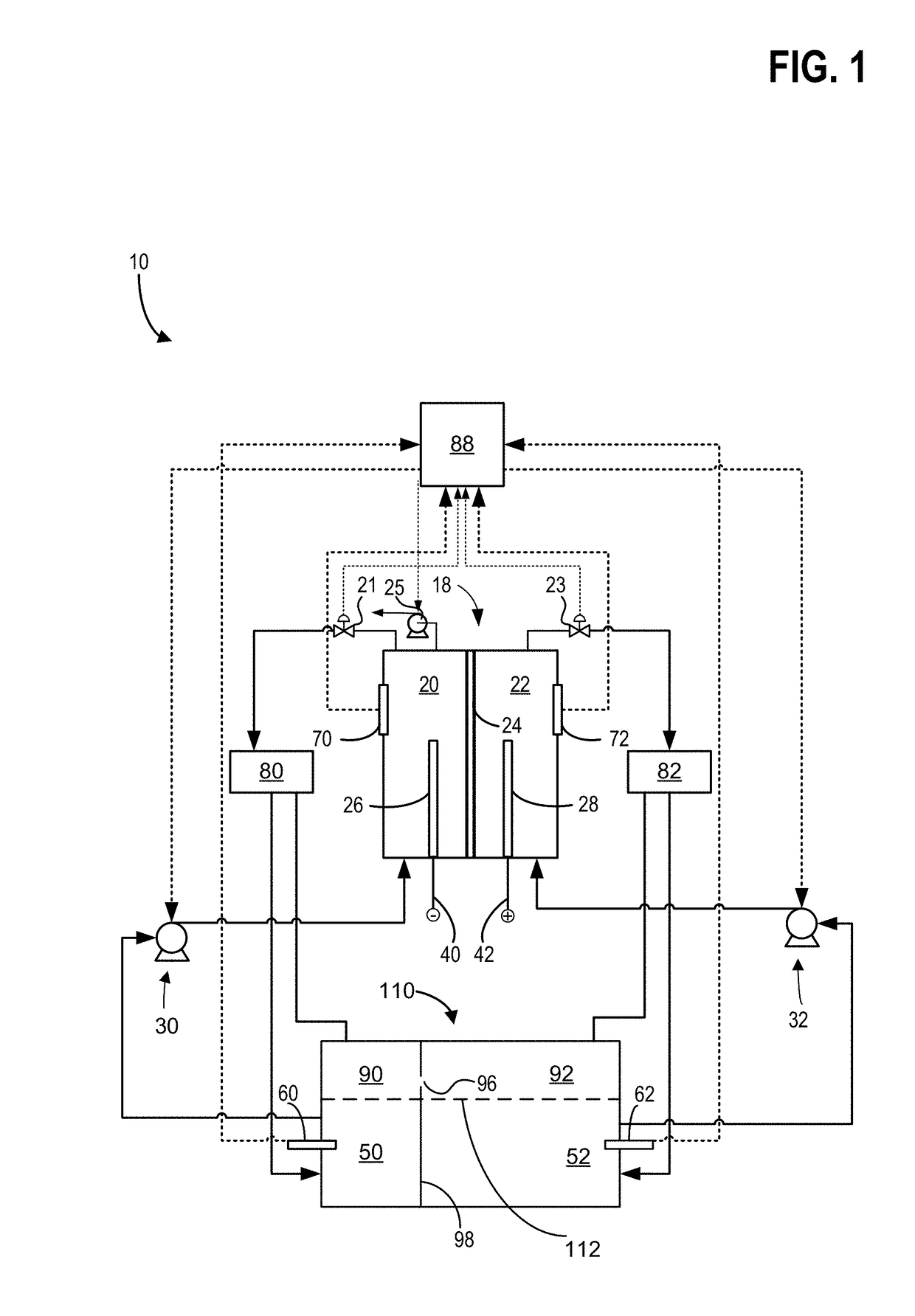
[0015]Hybrid redox flow batteries are redox flow batteries that are characterized by the deposition of one or more of the electro-active materials as a solid layer on an electrode. Hybrid redox flow batteries may, for instance, include a chemical that plates via an electrochemical reaction as a solid on a substrate throughout the battery charge process. During battery discharge, the plated species may ionize via an electrochemical reaction, becoming soluble in the electrolyte. In hybrid battery systems, the charge capacity (e.g., amount of energy stored) of the redox battery may be limited by the amount of metal plated during battery charge and may accordingly depend on the efficiency of the plating system as well as the available volume and surface area available for plating.

[0016]In a redox flow battery system the negative electrode 26 may be referred to as the plating electrode and the positive electrode 28 may be referred to as the redox electrode. The negative electrolyte withi...


PUM

PropertyMeasurementUnit
threshold cross-over pressureaaaaaaaaaa
resistanceaaaaaaaaaa
pressureaaaaaaaaaa

Abstract

A method of operating a redox flow battery, may include maintaining a positive electrode compartment pressure greater than a negative electrode compartment pressure, and maintaining a cross-over pressure less than a membrane break-through pressure, wherein the cross-over pressure equals the negative electrode compartment pressure subtracted from the positive electrode compartment pressure. In this way, ionic resistance across the separator can be maintained at a lower level by reducing gas bubbles trapped therein while reducing separator break-through, thereby increasing performance of the redox flow battery system.

Description

CROSS REFERENCE TO RELATED APPLICATIONS[0001]The present application claims priority to U.S. Provisional Application No. 62 / 491,963, entitled “Methods and Systems for Operating a Redox Flow Battery System”, and filed on Apr. 28, 2017. The entire contents of the above-listed application are hereby incorporated by reference for all purposes.ACKNOWLEDGMENT OF GOVERNMENT SUPPORT[0002]This invention was made with government support under contract No. DEAR0000261 awarded by the DOE, Office of ARPA-E. The government has certain rights in the invention.FIELD[0003]The present description relates generally to methods and systems for operating a redox flow battery system.BACKGROUND AND SUMMARY[0004]Redox flow batteries are suitable for grid scale storage applications due to their capabilities of scaling power and capacity independently, and charging and discharging for thousands of cycles with reduced performance losses as compared with conventional battery technologies. Redox flow battery cel...

Claims


Application Information

Patent Timeline
Patent Type & Authority Applications(United States)
IPC IPC(8): H01M8/04746H01M8/18H01M8/04082H01M8/04537
CPCH01M8/04783H01M8/188H01M8/04201H01M8/04641H01M8/04753H01M8/04186Y02E60/50
Inventor SONG, YANGDOREMUS, EVANGROBERG, THIAGO
Owner ESS TECHNOLOGY
Why Eureka
Try Eureka