Non-volatile transistor element including a buried ferroelectric material based storage mechanism

a technology of ferroelectric material and storage mechanism, which is applied in the direction of digital storage, semiconductor devices, instruments, etc., can solve the problems of data storage restriction, scaling of advanced semiconductor devices, and compatibility with a plurality of applications, and achieves superior flexibility, high efficiency, and superior flexibility in the design of respective soi storage.

Active Publication Date: 2018-11-08
GLOBALFOUNDRIES US INC
View PDF5 Cites 3 Cited by
  • Summary
  • Abstract
  • Description
  • Claims
  • Application Information

AI Technical Summary

Benefits of technology

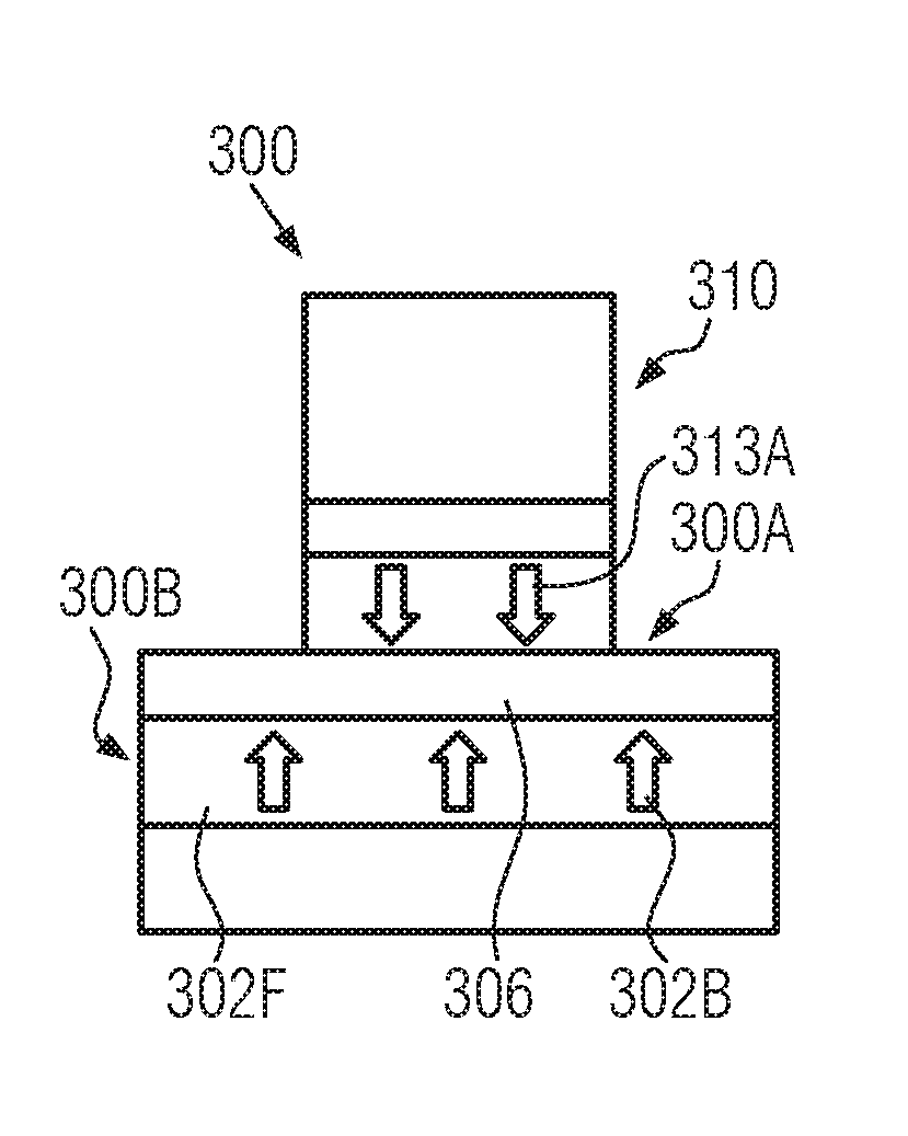
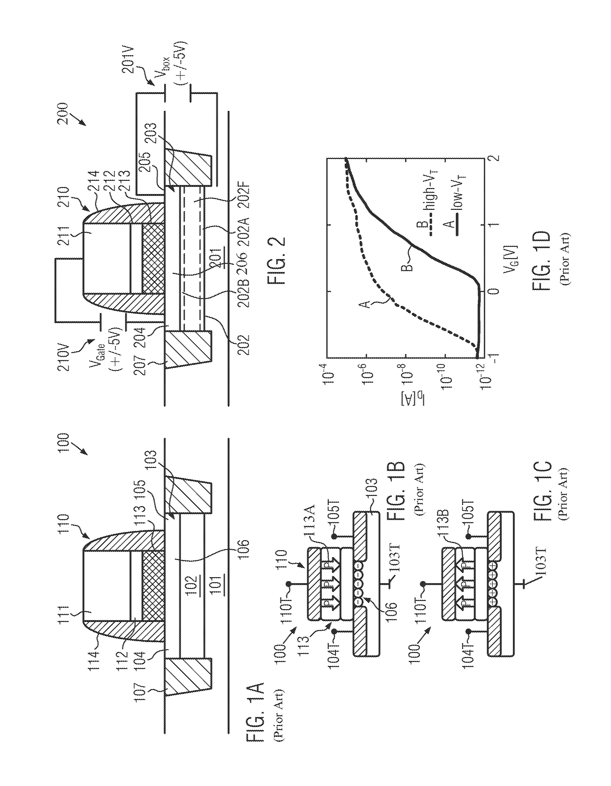
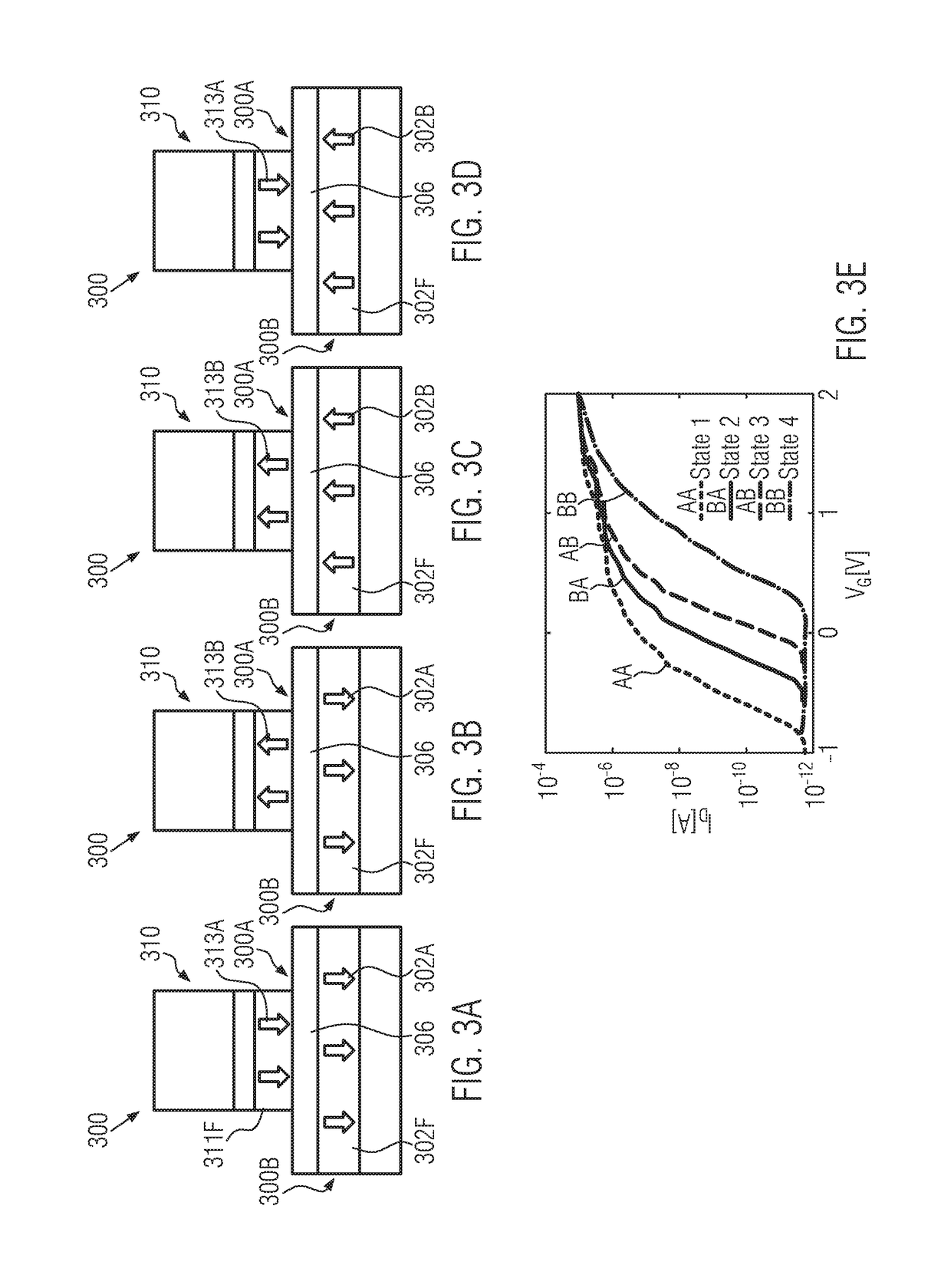
[0023]Basically, it has been recognized that, in SOI architectures, the highly efficient storage mechanism on the basis of a ferroelectric material may be implemented in the buried insulating layer of the SOI configuration, thereby contributing to the superior flexibility in designing respective SOI storage transistors. For example, the superior flexibility associated with the implementation of the storage mechanism into the buried insulating layer may result in less critical process techniques for forming sophisticated gate electrode structures of reduced dimensions, thereby potentially contributing to superior operational behavior due to a substantially non-changed overall electrode configuration, while still providing a non-volatile storage mechanism. In other illustrative embodiments, the storage mechanism implemented on the basis of a buried insulating layer may be efficiently combined with a further non-volatile storage mechanism, so that, in total, an increased bit density may be obtained. In some illustrative embodiments, the storage mechanism based on the buried insulating layer may be combined with a storage mechanism implemented in the gate electrode structure based on a ferroelectric material provided therein, while, in other illustrative embodiments, well-established floating gate configurations may be supplemented by the ferroelectric material based storage mechanism in the buried insulating layer, thereby also enhancing overall efficiently of these conventional floating gate approaches.

Problems solved by technology

Although the above-specified storage technique may represent a highly efficient mechanism that may be readily implemented in any type of integrated circuit, data storage is restricted to the times of supplying voltage to the device due to the volatile nature of this mechanism, since any information is lost upon switching off the supply voltage.
Since a permanent storage of logic states, in combination with the capability of their programmability, is frequently necessary, many non-volatile data storage techniques have been developed, wherein, in particular, many mass storage systems on the basis of magnetic storage devices, optical storage techniques and the like, may not be compatible with a plurality of applications due to the significant overhead in terms of hardware and software and, in particular, in terms of the moderately long access times. Therefore, significant efforts have been made in order to implement non-volatile storage mechanisms so as to complement or replace less time-efficient storage structures.
Although such storage transistors of flash memory structures, in which charges may be trapped or released from a specific portion of a gate electric structure of the transistor, may represent a very efficient solution for storing a single bit of information, it, nevertheless, turns out that, in particular, the ongoing scaling of advanced semiconductor devices may result in significant difficulties.
Therefore, implementation of such floating gate-type storage transistors may result in significant challenges, thereby necessitating additional efforts and adding complexity to the manufacturing processes.
Furthermore, in other cases, an SOI architecture may not be implemented and the semiconductor layer 103 may be formed above or as a part of the substrate material 101.

Method used


Image

  • Non-volatile transistor element including a buried ferroelectric material based storage mechanism
  • Non-volatile transistor element including a buried ferroelectric material based storage mechanism
  • Non-volatile transistor element including a buried ferroelectric material based storage mechanism

Examples


Embodiment Construction

[0035]Various illustrative embodiments of the invention are described below. In the interest of clarity, not all features of an actual implementation are described in this specification. It will of course be appreciated that in the development of any such actual embodiment, numerous implementation-specific decisions must be made to achieve the developers' specific goals, such as compliance with system-related and business-related constraints, which will vary from one implementation to another. Moreover, it will be appreciated that such a development effort might be complex and time-consuming, but would nevertheless be a routine undertaking for those of ordinary skill in the art having the benefit of this disclosure.

[0036]The present disclosure will now be described with reference to the attached figures. Various structures, systems and devices are schematically depicted in the drawings for purposes of explanation only and so as to not obscure the present disclosure with details whic...


PUM


Abstract

The present disclosure provides storage elements, such as storage transistors, wherein at least one storage mechanism is provided on the basis of a ferroelectric material formed in the buried insulating layer of an SOI transistor architecture. In further illustrative embodiments, one further storage mechanism is implemented in the gate electrode structure, thereby providing increased overall information density. In some illustrative embodiments, the storage mechanism in the gate electrode structure is provided in the form of a ferroelectric material.

Description

BACKGROUND1. Field of the Disclosure[0001]Generally, the present disclosure relates to techniques for providing a non-volatile storage mechanism in a circuit element, such as a field effect transistor, by taking advantage of the characteristics of a ferroelectric material.2. Description of the Related Art[0002]In many types of electronic components, data storage techniques may have to be implemented in order to guarantee the proper functioning of a respective technical system. For example, in many applications, different types of information have to be processed and, therefore, stored, which is typically accomplished on the basis of digital data. A basic entity of information may be considered as an entity having the capability of taking on different logic states so that implementation of respective logic states in hardware requires an appropriate electronic configuration that is capable of “occupying” respective different physical states, such as different voltage states, current s...

Claims


Application Information

Patent Timeline
Patent Type & Authority Applications(United States)
IPC IPC(8): G11C11/22H01L29/78G11C16/04G11C16/06
CPCG11C11/225H01L29/78391G11C16/06G11C16/0466H01L29/7841H10B43/30H10B51/30G11C11/005G11C11/5657G11C16/10G11C11/223G11C11/2275H01L29/792H01L29/40117H01L29/40111
Inventor DUENKEL, STEFANILLGEN, RALFRICHTER, RALFJANSEN, SOEREN
Owner GLOBALFOUNDRIES US INC
Why Eureka
Try Eureka