Ring and process for producing the same

a technology of ring and process, applied in the field of jewelry rings, can solve the problems of adversely affecting the wearing comfort and high material cost, and achieve the effects of high corrosion resistance, optimal surface characteristics, and advantageous overall visual appearance of jewelry rings

Inactive Publication Date: 2018-11-15
FURRER JACOT
View PDF7 Cites 0 Cited by
  • Summary
  • Abstract
  • Description
  • Claims
  • Application Information

AI Technical Summary

Benefits of technology

[0005]The invention seeks to remedy this. The object of the invention is to provide a jewelry ring and a method for manufacturing same, which overcomes these disadvantages, but at the same time maintains, or even improves, the high corrosion resistance, the optimal surface characteristics and the advantageous overall visual appearance of the jewelry ring.
[0012]the average specific density of the jewelry ring is significantly reduced as compared to pure metal rings;
[0013]the total weight of the jewelry ring is significantly reduced as compared to pure metal rings;
[0014]the material costs for manufacturing the jewelry ring are considerably reduced.
[0037]In one particular embodiment, a circular ring-like disk, which has an outer diameter larger than the jewelry ring, may be temporarily fastened to one or both lateral surfaces. This measure prevents the bundle from being wound beyond the lateral surfaces of the ring.

Problems solved by technology

The disadvantage of such precious metal jewelry rings is, on the one hand, the high material costs and, on the other hand—as a result of the very high specific density of the metals used—their high absolute weight, in particular, in the case of wide, weighty embodiments, which may adversely affect the wearing comfort.

Method used


Image

  • Ring and process for producing the same
  • Ring and process for producing the same
  • Ring and process for producing the same

Examples


Embodiment Construction

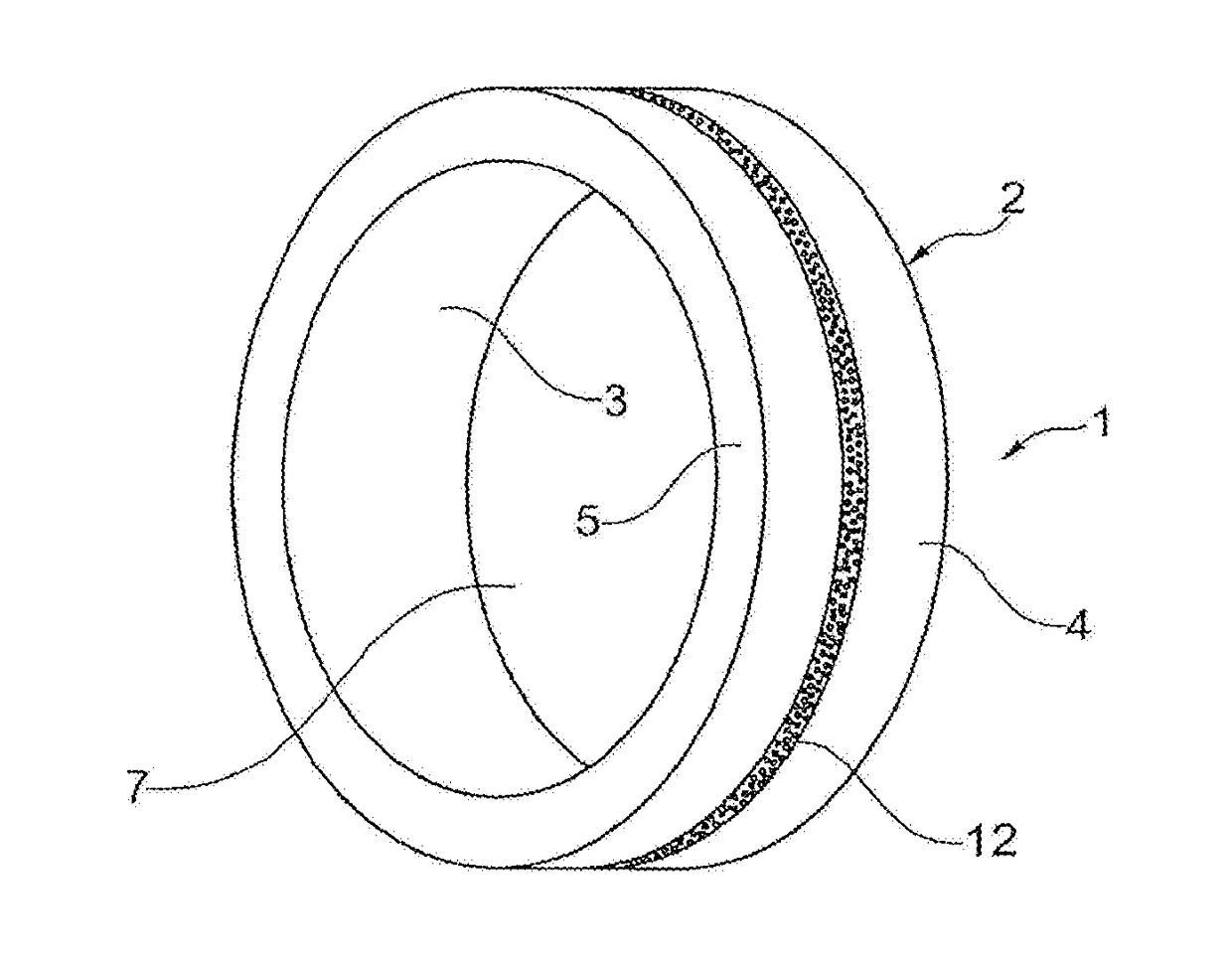
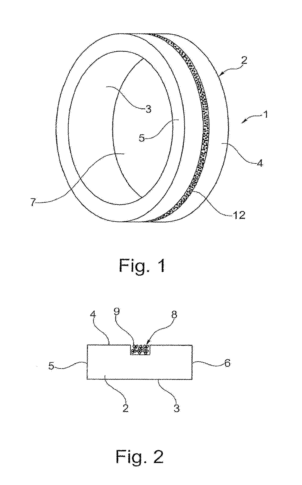
[0047]The jewelry ring 1 depicted in FIGS. 1 and 2 consist of an annular substrate 2 made of palladium, which has a peripherally circumferential groove 10, in which a roving consisting of a bundle 8 of axially twisted fibers 9 made of carbon having a specific weight of 1.5 g / cm3, and a diameter of 6 μm is wound with approximately 180-200 windings.

[0048]The fibers 9 are adhered to one another and to the groove 10 by means of a transparent epoxy resin adhesive. The peripheral-most fibers 9 are grounded off. The surface of the bundle 8 has a characteristic silk-like sheen.

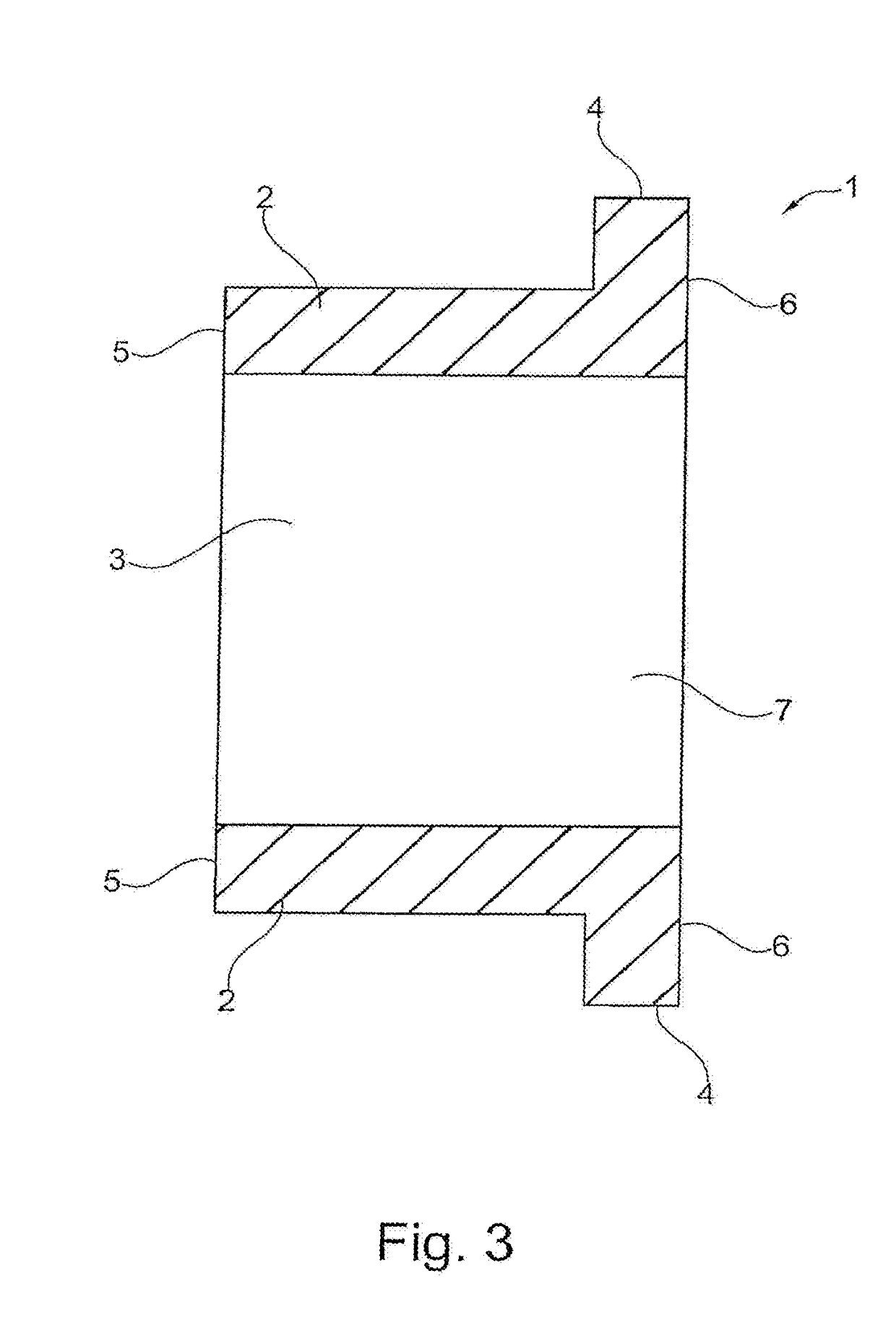
[0049]FIG. 3 shows a cross-section through a blank for another embodiment of the jewelry ring 1, in which the groove 10 is not bound on one side. To facilitate the winding of the roving, a washer having a diameter corresponding approximately to the right side of the blank is fastened to or pressed onto the left (open) side of the groove 10 during manufacture.

[0050]FIG. 4 depicts a blank for another embodiment of the j...


PUM

PropertyMeasurementUnit
densitiesaaaaaaaaaa
densitiesaaaaaaaaaa
densitiesaaaaaaaaaa

Abstract

A jewelry ring that includes a sleeve-like or annular substrate made of a precious metal or a precious metal alloy having a specific density ρ1, and which has an inner surface for contacting a finger, an outer surface, two lateral surfaces and a central cavity for accommodating the finger. A bundle of fibers is wound in multiple windings on at least a part of the outer surface. The fibers are connected to one another by a plastic adhesive having a specific density of ρ2<ρ1. The fibers have a specific density ρ3<ρ1. Also a method for manufacturing a jewelry ring, which includes wetting the bundle of fibers with plastic adhesive, fastening a start of the bundle to the sleeve-like or annular substrate, winding the bundle on the sleeve-like or annular substrate, applying pressure to the bundle, curing the plastic adhesive and grinding off peripheral-most fibers.

Description

CROSS-REFERENCE TO RELATED APPLICATIONS[0001]This application is a division of U.S. application Ser. No. 14 / 650,497, filed Jun. 8, 2015, which application is a U.S. national stage of PCT / CH2013 / 000206, filed Dec. 2, 2013, and claims priority to DE 10 2013 008 188.2, filed May 14, 2013 and CH 02908 / 12, filed Dec. 20, 2012.BACKGROUND OF INVENTION[0002]The invention relates to a jewelry ring and a method for manufacturing the same.[0003]Jewelry rings are crafted predominantly from the precious metals gold, platinum, palladium and alloys thereof, which are marked by their high resistance to corrosion, which also ensures a perfect surface of the metal over a very long period of time.[0004]The disadvantage of such precious metal jewelry rings is, on the one hand, the high material costs and, on the other hand—as a result of the very high specific density of the metals used—their high absolute weight, in particular, in the case of wide, weighty embodiments, which may adversely affect the w...

Claims


Application Information

Patent Timeline
Patent Type & Authority Applications(United States)
IPC IPC(8): A44C9/00A44C27/00B32B37/14B32B38/00B32B37/10B32B37/24
CPCA44C27/007A44C9/00B32B2451/00B32B37/142B32B38/0012B32B37/10B32B37/24B32B2038/0016
Inventor RUPPLI, LUCAS
Owner FURRER JACOT
Why Eureka
Try Eureka