Mobile robotic drilling apparatus and method for drilling ceilings and walls

a robotic drilling and ceiling technology, applied in the direction of programmed manipulators, turning machine accessories, manufacturing tools, etc., can solve the problems of high dust levels, difficult operation, and time-consuming marking up process, and achieve the effect of accurate drilling

Pending Publication Date: 2018-11-15
HILTI CORPOARATION
View PDF18 Cites 56 Cited by
  • Summary
  • Abstract
  • Description
  • Claims
  • Application Information

AI Technical Summary

Benefits of technology

[0048]In this way, accurate drilling can be achieved even when the robotic arm is reaching to long distances on a conventional lifting mechanism, such as a scissor...

Problems solved by technology

By the very nature of drilling holes in ceilings in particular, it is a difficult operation with the workman usually having to stand on a ladder or platform to reach the drilling points, and then lift heavy drilling equipment above his or her head.
The work usually creates high levels of dust and there will be minimum health and safety requirements that the workman will have to adhere to, such as ear, eye and breathing protection.
The marking up process in particular is very time consuming and the eventual positioning of the drilled holes, their depths and accuracy of drilling angle, is all subject to the workman's skill.
When drilling, one of the main problems i...

Method used


Image

  • Mobile robotic drilling apparatus and method for drilling ceilings and walls
  • Mobile robotic drilling apparatus and method for drilling ceilings and walls
  • Mobile robotic drilling apparatus and method for drilling ceilings and walls

Examples


Embodiment Construction

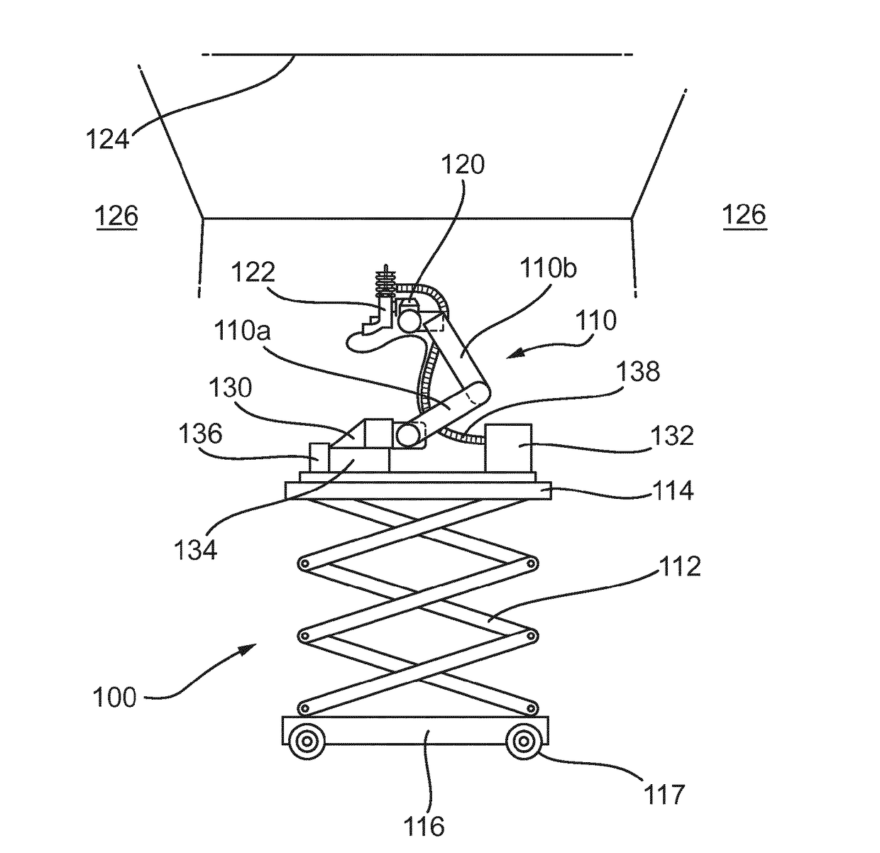
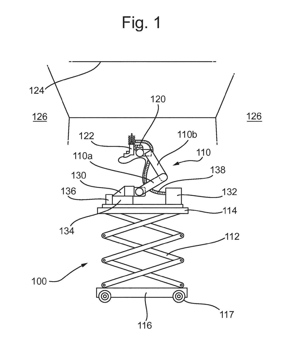
[0064]One aspect of a preferred embodiment of the present invention is shown generally in FIG. 1.

[0065]In this embodiment, there is provided a robotic drilling apparatus 100 having a robotic arm 110, with one end (a base end 110a) mounted to a substructure 112 and a moveable end 110b of the robotic arm 110 connected to a mount 120 for holding a drilling device 122.

[0066]A processor, not shown, can control the movement of the robotic arm 110 and the substructure 112 in order to manoeuvre the drilling device 122 to drill into a ceiling 124 or wall 126. For example, the height of the substructure 112 can be adjusted to move the drilling device 122 in a vertical direction towards a ceiling 124 or to a specific height on a wall 126. The robotic arm 110 can also be adjusted along various axes to position, orientate and move the drilling device 122 with respect to a ceiling or wall for drilling holes therein.

[0067]As shown in FIG. 1, the robotic arm 110 may be mounted on the substructure 1...


PUM

PropertyMeasurementUnit
Weightaaaaaaaaaa
Weightaaaaaaaaaa
Angleaaaaaaaaaa

Abstract

A robotic drilling apparatus is described which has been adapted for drilling holes in ceilings and walls on a construction site. The apparatus (100) comprises a robotic arm (110) mounted to a substructure (112), the substructure comprising a lifting mechanism arranged to lift the robotic arm to a working position, wherein the robotic arm has a base end (110a) and a movable end (110b), the base end being mounted to an upper surface (114) of the lifting mechanism and the movable end being capable of movement with respect to the base end in a three dimensional space, wherein the robotic drilling apparatus further comprises a mount (120) provided on the movable end for holding a drilling device (122) and a control unit (134) for controlling the operation of the robotic arm. The lifting mechanism preferably comprises a scissor-jack lifting platform. The robotic arm (110) and any support structure (134) for the robotic arm weighs less than 43 kg, and preferably individually weigh less than 23 kg.

Description

TECHNICAL FIELD[0001]The present invention relates to a mobile robotic drilling apparatus for drilling ceilings and walls, as well as to a method of drilling using the apparatus. It further relates to a vibration reducing assembly and to a mobile robotic drilling apparatus employing the same.BACKGROUND[0002]During construction of a building, particularly a large building such as a new office space, a shopping mall, etc., a considerable amount of labour is expended during the measuring up of surfaces, in particular ceilings and walls, and the subsequent drilling of holes for the mounting of components and building infrastructure, such as for wiring, pipes for water and waste, heating / cooling fluids, conduits for air conditioning, and of course equipment like pumps, controllers etc. associated with those services. This list is, of course, by no means exhaustive of the possibilities.[0003]By the very nature of drilling holes in ceilings in particular, it is a difficult operation with t...

Claims


Application Information

Patent Timeline
IPC IPC(8): B23B39/14B23B39/08B25J9/00
CPCB23B39/14B23B39/08B25J9/0027B08B15/04B25J11/005B25H1/0035B23B2226/75B66F7/0666B25J9/0009Y10S408/712Y10T408/935
Inventor HALVORSEN, HAVARDHENNINGE, TOM ASLEFAGERTUN, KONRAD
Owner HILTI CORPOARATION
Why Eureka
Try Eureka