Ignition plug and method for manufacturing ignition plug

a technology of ignition plugs and manufacturing methods, which is applied in the manufacture of sparking plugs, instruments, signs, etc., can solve the problems of reducing and achieve the effect of suppressing the decrease in the strength of the member having the mark and improving the reading accuracy relative to the portion adjacent to the periphery of the mark

Active Publication Date: 2018-11-15
NGK SPARK PLUG CO LTD
View PDF9 Cites 7 Cited by
  • Summary
  • Abstract
  • Description
  • Claims
  • Application Information

AI Technical Summary

Benefits of technology

[0006]In order to achieve this advantage, there is provided an ignition plug according to the present invention is configured to ignite an air-fuel mixture in an internal combustion engine. The ignition plug includes a mark that is formed of an oxide film generated on a surface of a metal member or is formed of the metal member and the oxide film.
[0007]According to the present invention, there is provided a method for manufacturing an ignition plug configured to ignite an air-fuel mixture in an internal combustion engine. The method includes a preparation step of preparing a metal member that constitutes a part of the ignition plug, and a marking step of forming a mark that is formed of an oxide film or is formed of the metal member and the oxide film by radiating a laser beam onto a surface of the metal member.
[0008]According to a first aspect, in the ignition plug, the mark is firmed of the oxide film generated on the surface of the metal member or is formed of the metal member and the oxide film. Thus, the decrease in the strength of the member having the mark can be suppressed compared with a case in which the mark is provided on a ceramic member.
[0009]According to a second aspect, in the ignition plug, the mark includes a first portion, and a second portion having a reflectance higher than a reflectance of the first portion. A variation of distribution of the reflectance of the first portion or a variation of distribution of the reflectance of the second portion is smaller than a variation of distribution of a reflectance of a portion on the surface of the metal member adjacent to a periphery of the mark or a variation of distribution of a reflectance of an oxide film adjacent to a periphery of the mark.
[0010]Therefore, when the mark is read by detecting beams of reflected light, a threshold can be set by using the distribution of the reflectance. Thus, in addition to the advantage of the first aspect, the mark reading accuracy relative to the portion adjacent to the periphery of the mark can be improved.
[0011]According to a third aspect, in the ignition plug, the variation of the distribution of the reflectance of the first portion d the variation of the distribution of the reflectance of the second portion are smaller than the variation of the distribution of the reflectance of the portion on the surface of the metal member adjacent to the periphery of the mark or a variation of distribution of a reflectance of an oxide film adjacent to a periphery of the mark.

Problems solved by technology

Therefore, the mark may trigger breaking of the base, thereby causing a risk that the strength of the member having the mark may decrease.

Method used


Image

  • Ignition plug and method for manufacturing ignition plug
  • Ignition plug and method for manufacturing ignition plug
  • Ignition plug and method for manufacturing ignition plug

Examples


Embodiment Construction

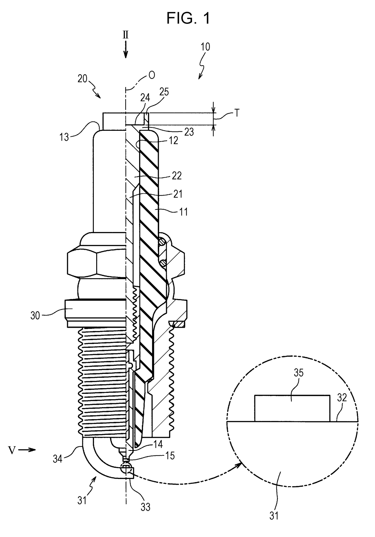
[0034]A preferred embodiment of the present invention is described below with reference to the accompanying drawings. FIG. 1 is a half sectional view of an ignition plug 10 according to one embodiment of the present invention. In FIG. 1, the lower side of the drawing sheet is referred to as a front end side of the ignition plug 10 and the upper side of the drawing sheet is referred to as a rear end side of the ignition plug 10. The ignition plug 10 is configured to ignite an air-fuel mixture in an internal combustion engine (not illustrated). The ignition plug 10 includes an insulator 11, a metal terminal 20, a metal shell 30, and a ground electrode 31.

[0035]The insulator 11 is a cylindrical member formed of, for example, alumina that is excellent in mechanical properties and insulation properties under high temperature. An axial hole 12 is formed through the insulator 11 along an axial line O. A center electrode 14 is arranged on the front end side of the axial hole 12.

[0036]The ce...


PUM

PropertyMeasurementUnit
heightaaaaaaaaaa
reflectanceaaaaaaaaaa
brittleaaaaaaaaaa

Abstract

An ignition plug such as a spark plug or a glow plug configured to ignite an air-fuel mixture in an internal combustion engine includes a mark that is formed of an oxide film generated on the surface of a metal member or is formed of the metal member and the oxide film. The mark is formed by promoting formation of the oxide film on the surface of the metal member or removing the oxide film through radiation of a laser beam onto the surface of the metal member.

Description

RELATED APPLICATIONS[0001]This application claims the benefit of Japanese Patent Application No. 2017-094516, filed May 11, 2017, the entire contents of which are incorporated herein by reference.FIELD OF THE INVENTION[0002]The present invention relates to an ignition plug and a method for manufacturing the ignition plug, and more particularly, to an ignition plug having a mark and a method for manufacturing the ignition plug.BACKGROUND OF THE INVENTION[0003]There is a technology in which a predefined identifier (mark) is provided on an industrial product and background information on the industrial product becomes traceable throughout procurement, processing, production, distribution, sales, disposal, and the like. Ignition plugs configured to ignite air-fuel mixtures in internal combustion engines are also required to have marks in order to increase the traceability. As a technology for providing a mark on an industrial product, Japanese Registered Utility Model No. 3078913 disclo...

Claims


Application Information

Patent Timeline
Patent Type & Authority Applications(United States)
IPC IPC(8): H01T21/02G06K1/12B23K26/00H01T13/02B23K26/40G06K19/06
CPCH01T21/02G06K1/128B23K26/40B23K2103/50H01T13/02B23K26/355B23K26/359G06K19/06046B23K26/0006B23K26/083B41M5/24B41M5/262B23K26/352B23K26/364B23K2101/35B23K2101/36B23K2103/04C21D10/005G09F7/165H01T13/04H01T13/20H01T13/32H01T13/58
Inventor MAKI, SHUNSUKE
Owner NGK SPARK PLUG CO LTD
Why Eureka
Try Eureka