Signal processing circuit and method

Inactive Publication Date: 2018-11-22
SONY CORP
View PDF4 Cites 7 Cited by
  • Summary
  • Abstract
  • Description
  • Claims
  • Application Information

AI Technical Summary

Benefits of technology

[0020]According to the present technology, it is possible to generate a stable physical unclonable function (PUF) being less susceptible to environmental changes and having less deterioration in characteristics.
[0021]Note that effects described here in the

Problems solved by technology

In addition, a PUF technology (non-patent document 2) based on random

Method used


Image

  • Signal processing circuit and method
  • Signal processing circuit and method
  • Signal processing circuit and method

Examples


Embodiment Construction

[0030]Hereinafter, embodiments of the present disclosure (hereinafter, embodiment(s)) will be described.

[0031]

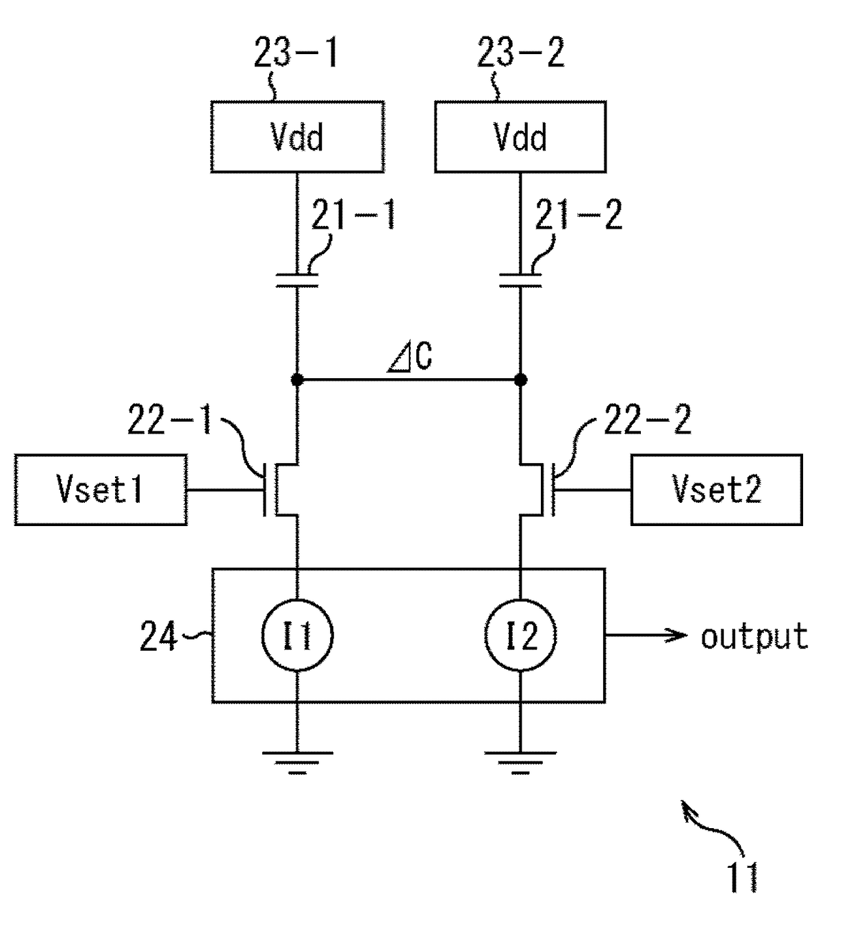
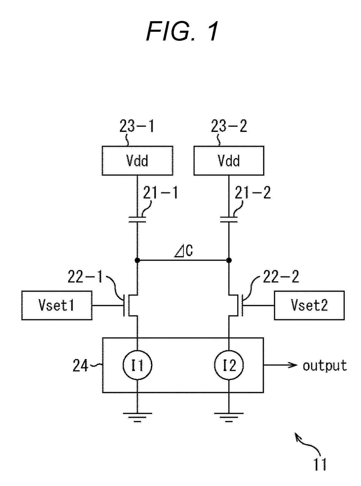
[0032]FIG. 1 is a circuit diagram illustrating an exemplary configuration of a differential pair circuit according to the present technology.

[0033]In the example of FIG. 1, a differential pair circuit 11 is a differential pair circuit including: DUT 21-1 and Tr 22-1 connected to VDD 23-1; DUT 21-2 and Tr 22-2 connected to VDD 23-2 arranged in pair with the VDD 23-1; and an output unit 24.

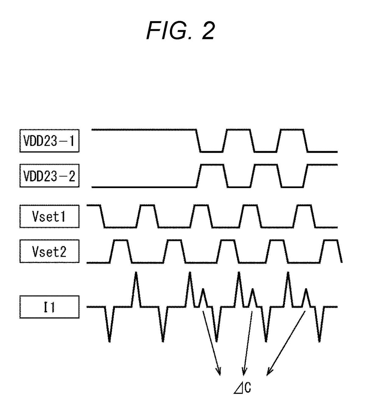
[0034]In the differential pair circuit 11, capacitance (MOS-C (gate capacitance), MIS-C (MIS type), Comb-C (MOM type wire), or the like) is arranged as DUT 21-1 and DUT 21-2. Tr 22-1 and Tr 22-2 are transistors, and pulses of Vset 1 and Vset 2 are applied to Tr 22-1 and Tr 22-2, respectively. VDD 23-1 and VDD 23-2 are power supply voltages. The output unit 24 outputs at least one of I1 and I2 to a subsequent stage (not illustrated).

[0035]As illustrated in the timing chart of FIG. 2, pulses o...


PUM


Abstract

The present disclosure relates to a signal processing circuit and method for the same capable of generating a stable physical unclonable function (PUF) being less susceptible to environmental changes and having less characteristic deterioration. Two VDDs are voltages alternately inverted. The two VDDs perform charge and discharge such that one is turned on while the other is turned off, and a current flows by a difference at an edge during switching (inversion). The output I1 is proportional to a capacitance value difference between the pair of DUTs, and the capacitance value difference between the pair of DUTs can be obtained by ΔC=ΔI/(VDD*f). The present technology is applicable to a signal processing circuit on which a differential pair is mounted, for example.

Description

TECHNICAL FIELD[0001]The present disclosure relates to a signal processing circuit and a method for the same and more particularly relates to a signal processing circuit and a method for the same, capable of generating a stable physical unclonable function (PUF) being less susceptible to environmental changes and having less characteristic deterioration.BACKGROUND ART[0002]In recent years, a physical unclonable function (PUF) is used in IC tags, authentication security systems, LSI counterfeit prevention, or the like. Examples of these are a smart card (non-patent document 1) using SRAM, and arbiter PUF.[0003]In addition, a PUF technology (non-patent document 2) based on random telegraph noise (RTN) has been reported as not being commercialized.[0004]Meanwhile, there is a proposed method of a difference charge-based capacitance measurement (DCBCM) method (refer to Patent Document 1 and Non-Patent Document 3) capable of detecting an extremely small capacitance difference of aF level....

Claims


Application Information

Patent Timeline
IPC IPC(8): H04L9/32
CPCH04L9/3278G09C1/00
Inventor AMMO, HIROAKISAWADA, KEN
Owner SONY CORP
Why Eureka
Try Eureka