Electric working machine, and method for determining load-imposed state of electric working machine

a technology of electric working machine and load-imposed state, which is applied in the direction of electronic commutators, portable power-driven tools, instruments, etc., can solve problems such as affecting the accuracy of determination, and achieve the effect of improving the accuracy of determination and simplifying the configuration of electric working machines

Active Publication Date: 2018-11-29
MAKITA CORP
View PDF0 Cites 4 Cited by
  • Summary
  • Abstract
  • Description
  • Claims
  • Application Information

AI Technical Summary

Benefits of technology

[0022]Such a load-determiner is able to make a determination without changing the threshold value based on the threshold value that is fixed. This consequently helps to simplify the configuration of the electric working machine.
[0023]In an alternative case where the load-determiner is configured to change the threshold value between the high-speed rotation mode and the low-speed rotation mode, accuracy of the determination can be improved.

Problems solved by technology

However, when the determination is made based on an unprocessed detection signal from the acceleration sensor, unwanted signal components included in the detection signal may hinder accurate determination.

Method used


Image

  • Electric working machine, and method for determining load-imposed state of electric working machine
  • Electric working machine, and method for determining load-imposed state of electric working machine
  • Electric working machine, and method for determining load-imposed state of electric working machine

Examples


Embodiment Construction

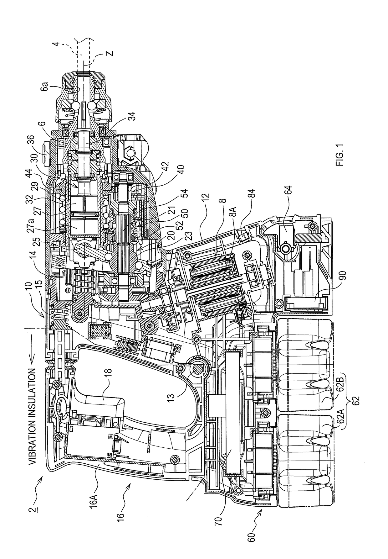
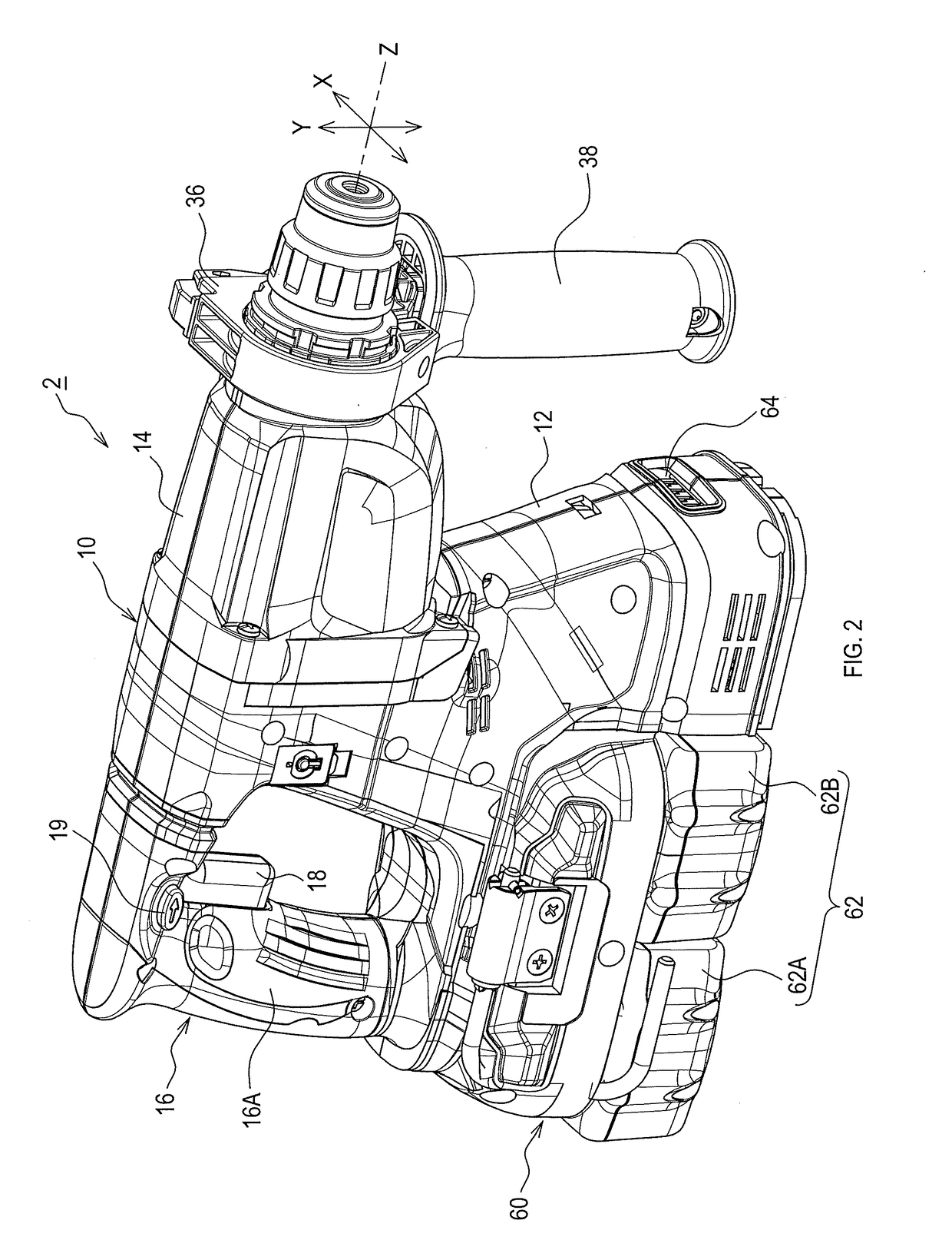
[0039]A hammer drill 2 of the present embodiment is configured to perform chipping or drilling on a work piece (e.g., concrete) by a hammering by a tool bit 4, such as a hammer bit, along the longer axis of the tool bit 4 or rotating it about the longer axis.

[0040]As shown in FIG. 1, the hammer drill 2 includes a main body housing 10. The main body housing 10 defines the contour of the hammer drill 2. The tool bit 4 is detachably attached to the tip of the main body housing 10 through a tool holder 6. The tool holder 6 has a cylindrical shape and functions as an output shaft.

[0041]The tool bit 4 is inserted in a bit insertion hole 6a in the tool holder 6 and held by the tool holder 6. The tool bit 4 can reciprocate along the longer axis of the tool bit 4 against the tool holder 6, but the rotational motion of the tool bit 4 about the longer axis of the tool bit 4 against the tool holder 6 is restricted.

[0042]The main body housing 10 includes a motor housing 12, and a gear-housing 14...


PUM


Abstract

An electric working machine in one aspect of the present disclosure includes a motor; an acceleration sensor; a load-determiner; a filter part having a cutoff frequency; and a filter-property setting part. The filter part removes an unwanted signal component from a detection signal from the acceleration sensor based on the cutoff frequency and inputs, to the load-determiner, the detection signal with the unwanted signal component removed. The filter-property setting part changes the cutoff frequency of the filter part such that a cutoff frequency in a high-speed rotation mode is higher than a cutoff frequency in a low-speed rotation mode.

Description

CROSS-REFERENCE TO RELATED APPLICATIONS[0001]This application claims the benefit of Japanese Patent Application No. 2017-104495 filed May 26, 2017 in the Japan Patent Office, the disclosure of which is incorporated herein by reference.BACKGROUND[0002]The present disclosure relates to a technique of driving a motor of an electric working machine in a low-speed rotation mode when the electric working machine is placed in a no-load-imposed state and in a high-speed rotation mode when the electric working machine is placed in a load-imposed state.[0003]A hammering tool disclosed in Japanese Unexamined Patent Application Publication No. 2004-255542 is configured to reduce energy loss by driving a motor of the hammering tool in a low-speed rotation mode when the hammering tool is placed in no-load-imposed state, in which no hammering motion is performed. This hammering tool is also configured to improve its work efficiency by driving the motor in a high-speed rotation mode when the hammer...

Claims


Application Information

Patent Timeline
Patent Type & Authority Applications(United States)
IPC IPC(8): B23Q17/22B25D16/00G01H1/00B25D17/00H02P6/16
CPCB23Q17/22B25D16/00G01H1/003B25D17/00H02P6/16B25D2250/221B25D2250/201B25D11/06B25D17/24B25F5/00B25F5/026B25B21/02B25D2211/061B25D2216/0015B25D2216/0023B25D2216/0038
Inventor YAMAMOTO, HIROKATSUUMEMOTO, RYO
Owner MAKITA CORP
Why Eureka
Try Eureka