Integrated rail and track condition monitoring system with imaging and internal sensors

a condition monitoring system and integrated technology, applied in the direction of image enhancement, instruments, transportation and packaging, etc., can solve the problems of track components and assets degrade and endure damage, risk of complete failure or degradation, and material strength degradation, so as to improve the accuracy of track component location determination and enhance positioning accuracy

Active Publication Date: 2018-11-29
SINGH SAMEER
View PDF2 Cites 83 Cited by
  • Summary
  • Abstract
  • Description
  • Claims
  • Application Information

AI Technical Summary

Benefits of technology

[0050]The location determination system may comprise a vehicle travel distance sensor, such as a tachometer, and/or a track position sensor. This may be used in addition to, or instead of, a GPS or other geographic location system. Combining multiple location determination systems/sensor types may be used to increase the accuracy of track component location determination. A track position sensor may comprise a sensor for identifying track features indicative of known/predetermined track locations, e.g. fixed datum locations. One or more scanning sensor could be used for this purpose or else a near-field wireless communication transmitter receiver. An RFID sensor, for example, could be used to detect RFID tag

Problems solved by technology

Over time, track components and assets degrade and endure damage because of the physical stress caused by movement of trains, changes in weather conditions causing compression or expansion in materials, rain and environmental conditions, and degradation in material strength with age.
If the track and associated assets are not monitored effectively, then there is a risk of complete failure or degradation to the extent that a significant risk is posed to safe operation of the railroad.
Such form of inspection is costly, unsafe, slow and prone to human error.
Growth in rail networks, coupled with the time required for manual inspection has made it difficult in practice to carry out manual track inspection at the required inspection frequency with full network coverage.
The implementation and maintenance of such systems is costly, and time consuming.
In particular, such systems need extensive configuration to f

Method used


Image

  • Integrated rail and track condition monitoring system with imaging and internal sensors
  • Integrated rail and track condition monitoring system with imaging and internal sensors
  • Integrated rail and track condition monitoring system with imaging and internal sensors

Examples


Embodiment Construction

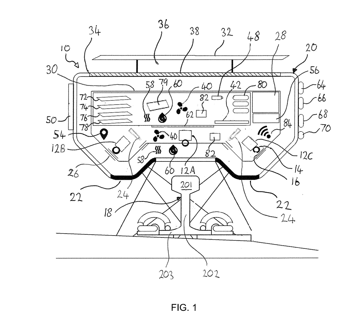
[0090]Examples of the invention described hereinbelow concern the use of a housed system for surveying railroad track, herein termed a “TrackVue” system. All the equipment required for scanning, processing and logging the visual and / or geometric features of railroad track are provided with a common support structure so as to allow for a system that can be installed on passenger trains and / or freight trains as well as, or instead of, being installed on dedicated inspection vehicles. A singular housed unit or installation of this kind is well suited for retrofitting on existing trains and can offer simple installation and operation. Systems according to examples of the invention may provide so-called ‘plug-and-play’ functionality when compared to the systems used in the prior art. The advantages of the support of the various different sensors on a common structure that is mountable to the exterior of a railroad vehicle are described hereinbelow.

[0091]Turning firstly to FIG. 1, the sys...


PUM


Abstract

A railroad track inspection system has multiple track scanning sensors, a data store, and a scan data processor. The scan data processor provides automatic analysis of the track scan data to detect track components within the scan data from a predetermined list of component types according to features identified in said scan data. The track scanning sensors, data store and scan data processor are attached to a common support structure for mounting the system to a railway vehicle in use. An inertia sensor and common master clock are used to make corrections to the output of the track scanning sensors to accommodate dynamic forces in use. The inspection system may be provided in a single housing for mounting to a conventional passenger/freight rail vehicles and may operate automatically in an unattended mode. The location of track components and/or defects may be logged.

Description

CLAIM OF PRIORITY[0001]This application is a continuation-in-part of the U.S. patent application Ser. No. 14 / 982,312 filed on Dec. 29, 2015, which claims priority to and the benefit of GB Application No. 1518599.4, filed on Oct. 20, 2015, and the disclosure of each of the applications above is incorporated herein by reference in its entirety.BACKGROUND1. Field of the Invention[0002]The present invention relates to apparatus for the surveying of railroad track, and more particularly, although not exclusively, apparatus for assessing track health based on inspection.2. Description of Related Art[0003]Railroad tracks, also known as ‘permanent way’, consist of rails, fasteners, sleepers (ties), ballast and the underlying subgrade. A wide variety of variations are possible in terms of types of rail used, jointed or continuous welded, use of sleepers with ballast or slab track, type of fastenings used, and switch layouts. A number of associated track assets are also mounted on conventiona...

Claims


Application Information

Patent Timeline
IPC IPC(8): B61L23/04B61L25/02G06K9/62G06V10/143G06V10/147G06V10/44G06V10/762G06V30/144
CPCB61L23/045B61L23/044B61L23/047B61L25/021G06K9/6215G06K9/6218B61K9/08G06T7/001G06T2207/10024G06T2207/30136G06V10/143G06V10/147G06V10/44G06V10/751G06V2201/06G06V10/762G06V10/803G06V10/809G06F18/23G06F18/251G06F18/254G06V30/144G06F18/22
Inventor SINGH, SAMEER
Owner SINGH SAMEER
Why Eureka
Try Eureka