Transmission system for converting signal of 9-channel encoder into 1000mbps phy signal

a technology of phy signal and transmission system, which is applied in the direction of electrical programme control, programme-controlled manipulators, programme control, etc., can solve the problems of system stability, difficult to achieve the existing speed (2.5 mbps), and poor stability, and achieve the effect of overcomplicating cable and expensive cost, high signal delay, and poor stability

Active Publication Date: 2018-11-29
HARBIN BO QIANG ROBOT TECH CO LTD +1
View PDF3 Cites 4 Cited by
  • Summary
  • Abstract
  • Description
  • Claims
  • Application Information

AI Technical Summary

Benefits of technology

[0004]In view of defects of the prior art, the object of the present invention is to provide a transmission system for converting a signal of a 9-channel encoder into ...

Problems solved by technology

Their transmission rates are limited to their transmission distances, and difficultly achieve the existing speed (2.5 Mbps) when the transmission distance is far.
For a multi-axis robot (a robot having 6˜9 axes), the above communication manner needs 6˜9 4-core cables independent each other for transmission, which is not beneficial to stability of the system, and the price of the cable is re...

Method used


Image

  • Transmission system for converting signal of 9-channel encoder into 1000mbps phy signal
  • Transmission system for converting signal of 9-channel encoder into 1000mbps phy signal

Examples


Embodiment Construction

[0015]Next, the present invention will be described in detail in combination with drawings and embodiments.

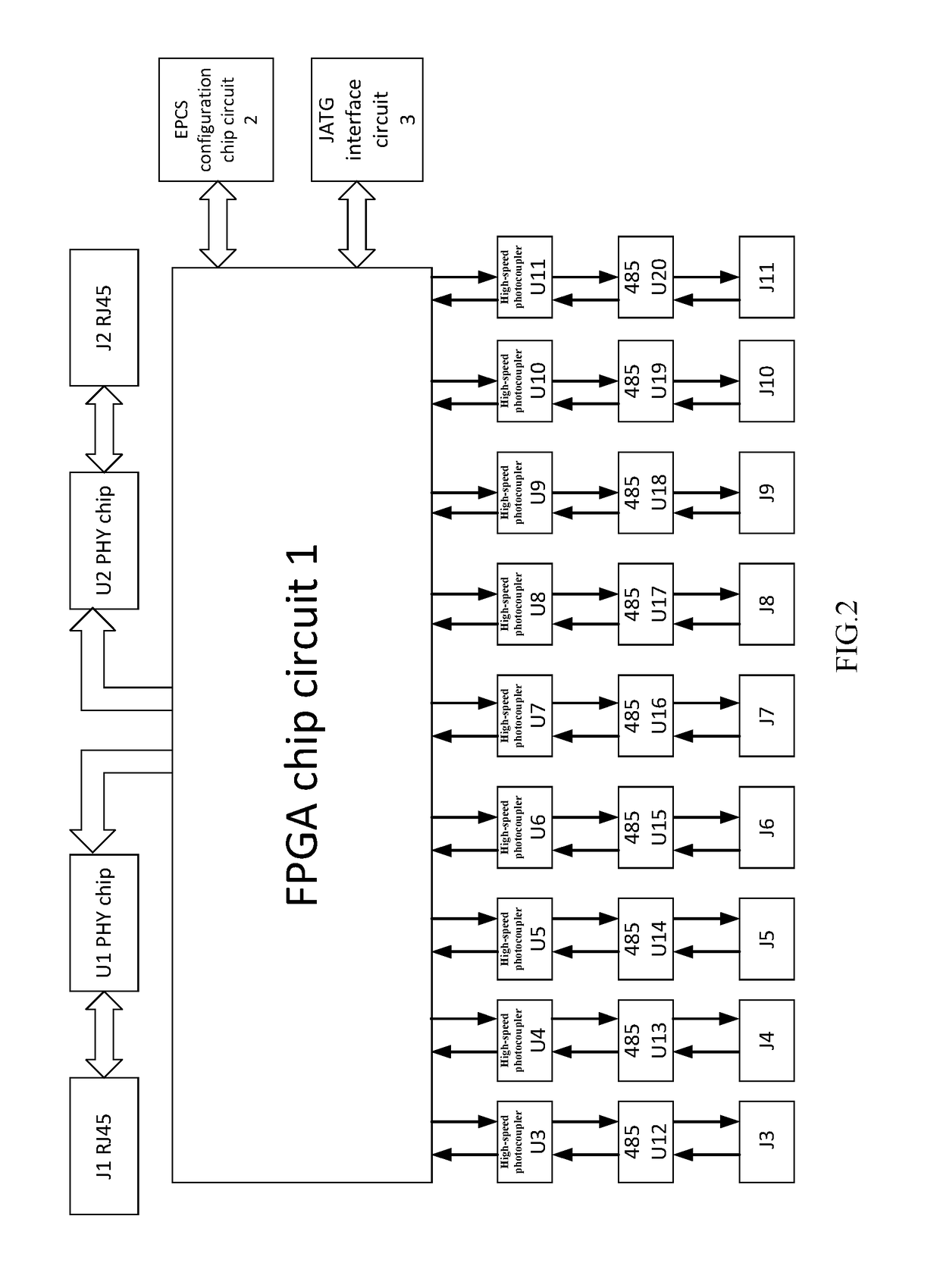
[0016]As shown in FIG. 1 and FIG. 2, a transmission system for converting a signal of a 9-channel encoder into a 1000 Mbps PHY signal includes PHY chip circuits U1 and U2, digital photocouplers U3˜U11, 485 transceivers U12˜U20, RJ45 isolation transformer-integrated jacks J1 and J2, an FPGA chip circuit 1, an EPCS configuration chip circuit 2, a Jtag interface 3 and SM-6P-PCB sockets J3˜J11, wherein

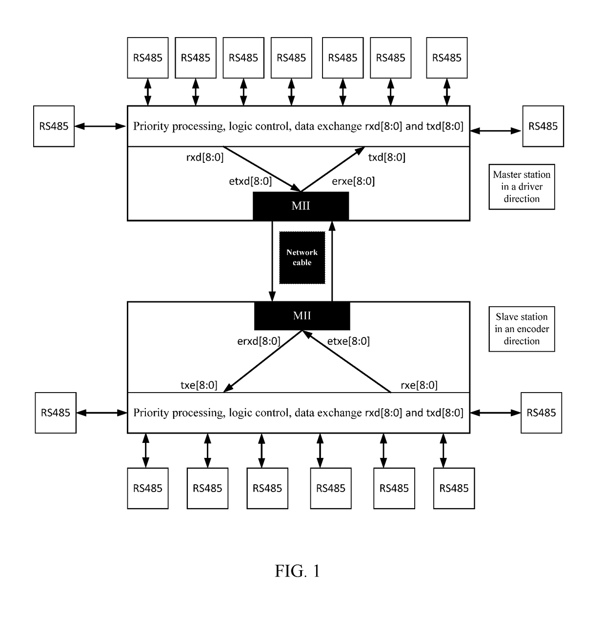
[0017]two-channel MII digital signal output and input ends of the FPGA chip circuit 1 are respectively connected with MII digital signal input and output ends of the PHY chip circuits U1 and U2; differential data signal output and input ends of the PHY chip circuits U1 and U2 are respectively connected to the RJ45 isolation transformer-integrated jacks J1 and J2; first-channel 485 digital signal input and output ends of the FPGA chip circuit 1 are connected with digital signal output ...


PUM


Abstract

A transmission system for converting a signal of a 9-channel encoder into a 1000 Mbps PHY signal, includes a PHY chip circuits U1 and U2, digital photocouplers U3˜U11, 485 transceivers U12˜U20, RJ45 isolation transformer-integrated jacks J1 and J2, a field programmable gate array (FPCiA) chip circuit, an electronic propulsion control system (EPCS) configuration chip circuit, a Jtag interface and SM-6P-PCB jackets J3˜J11, wherein two-channel MII digital signal output and input ends of the FPGA chip circuit are respectively connected with MII digital signal input and output ends of the PHY chip circuits U1 and U2; differential data signal output and input ends of the PHY chip circuits U1 and U2 are respectively connected to the RJ45 isolation transformer-integrated jacks J1 and J2, and a master station and a slave station are arranged at the same time.

Description

CROSS-REFERENCE TO RELATED APPLICATIONS[0001]This application is a continuation of International Patent Application No. PCT / CN2016 / 000284 with a filing date of May 27, 2016, designating the United States, now pending, and further claims priority to Chinese Patent Application No. 201610081951.5 with a filing date of Feb. 5, 2016 and Chinese Patent Application No. 201620117021.6 with a filing date of Feb. 5 2016. The content of the aforementioned applications, including any intervening amendments thereto, are incorporated herein by reference.TECHNICAL FIELD[0002]The present invention relates to a transmission system for converting a signal of a 9-channel encoder signals into a 1000 Mbps PHY signal and a method for the same, belonging to the technical field of robot data communication protocol conversion.BACKGROUND OF THE PRESENT INVENTION[0003]There are many existing absolute value encoder transmission protocols, such as an EnDat protocol, a BISS protocol and a RS485 protocol, and mos...

Claims


Application Information

Patent Timeline
IPC IPC(8): G05B19/416H04L29/08H04L29/06B25J9/16
CPCG05B19/416H04L67/12H04L69/08B25J9/1628G05B2219/39138
Inventor KONG, MINXIUZHOU, WENBIAOZHANG, YANQIN
Owner HARBIN BO QIANG ROBOT TECH CO LTD
Why Eureka
Try Eureka