Piezoelectric rotational MEMS resonator

a rotational, mems-resonator technology, applied in the field of mems-resonators, can solve the problems of not having an optimal bending mode, complicated contact arrangement, and the inability of the mems-resonator to be attached directly to the inertial

Active Publication Date: 2018-11-29
MURATA MFG CO LTD
View PDF0 Cites 19 Cited by
  • Summary
  • Abstract
  • Description
  • Claims
  • Application Information

AI Technical Summary

Problems solved by technology

In MEMS resonators piezoelectric transducers typically cannot be attached directly to the inertial mass because it is too rigid.
This is not an optimal bending mode because the sense voltage signal is lowered when charges of opposite sign cancel out in each sense electrode.
The problem may be alleviated by coating one suspender with two separate sense transducers to counter the charge reversal, but this requires complicated contacting arrangements.
The same problem occurs during in-plane rotation.
Another problem which arises from inflexible attachment and S-shaped bending is that the relationship between external force and suspender displacement becomes non-linear.
This effect is undesirable in applications where frequency stability or frequency tracking between two resonators is aimed at, as is the case for reference oscillators and gyroscopic sensors.
A third problem with the state of the art suspender and attachment is the relatively high spring constant produced by the S-shape mode of bending of the suspender.
However, the same technical problems arise in drive transducers, because the inertial mass cannot be driven to oscillate in resonance unless the suspender assumes the bending mode which the resonance oscillation of the inertial mass dictates.
The technical problems outlined above have in part retarded the development of piezoelectric rotational resonators.
Piezoelectric transduction could improve the performance of a resonator on all of these counts, but suspender design becomes critical.

Method used


Image

  • Piezoelectric rotational MEMS resonator
  • Piezoelectric rotational MEMS resonator
  • Piezoelectric rotational MEMS resonator

Examples


Embodiment Construction

Resonator Embodiment

[0055]This disclosure describes a rotational resonator comprising a substrate with one or more anchor points and an inertial mass with a first longitudinal end and a second longitudinal end. The inertial mass is suspended from the one or more anchor points by one or more suspenders extending from the one or more anchor points toward either the first longitudinal end or the second longitudinal end of the inertial mass. One or more of the suspenders are coated with a piezoelectric transducer structure configured to drive or detect oscillating rotary movement in the inertial mass. No more than one suspender is attached to any of the anchor points. The longitudinal length of each coated suspender is 0.5-1 times the longitudinal length of the inertial mass.

[0056]When piezoelectric transducers described in this disclosure are used in the sense mode, the best signal-to-noise ratios may be achieved when the transducer capacitance equals the sum of the capacitance of the ...


PUM


Abstract

This disclosure reveals a resonator where at least one suspended inertial mass is driven into rotational oscillation by a piezoelectric drive transducer, or where the rotational motion of at least one suspended inertial mass is sensed by a piezoelectric sense transducer. The disclosure is based on the idea of suspending the inertial mass with a one-sided suspender arrangement, where only one suspender is attached to each anchor point, and on the optimal positioning of the suspender in relation to the effective center of gravity of the resonator. The resonator may be employed in a resonator system, a clock oscillator or a gyroscope.

Description

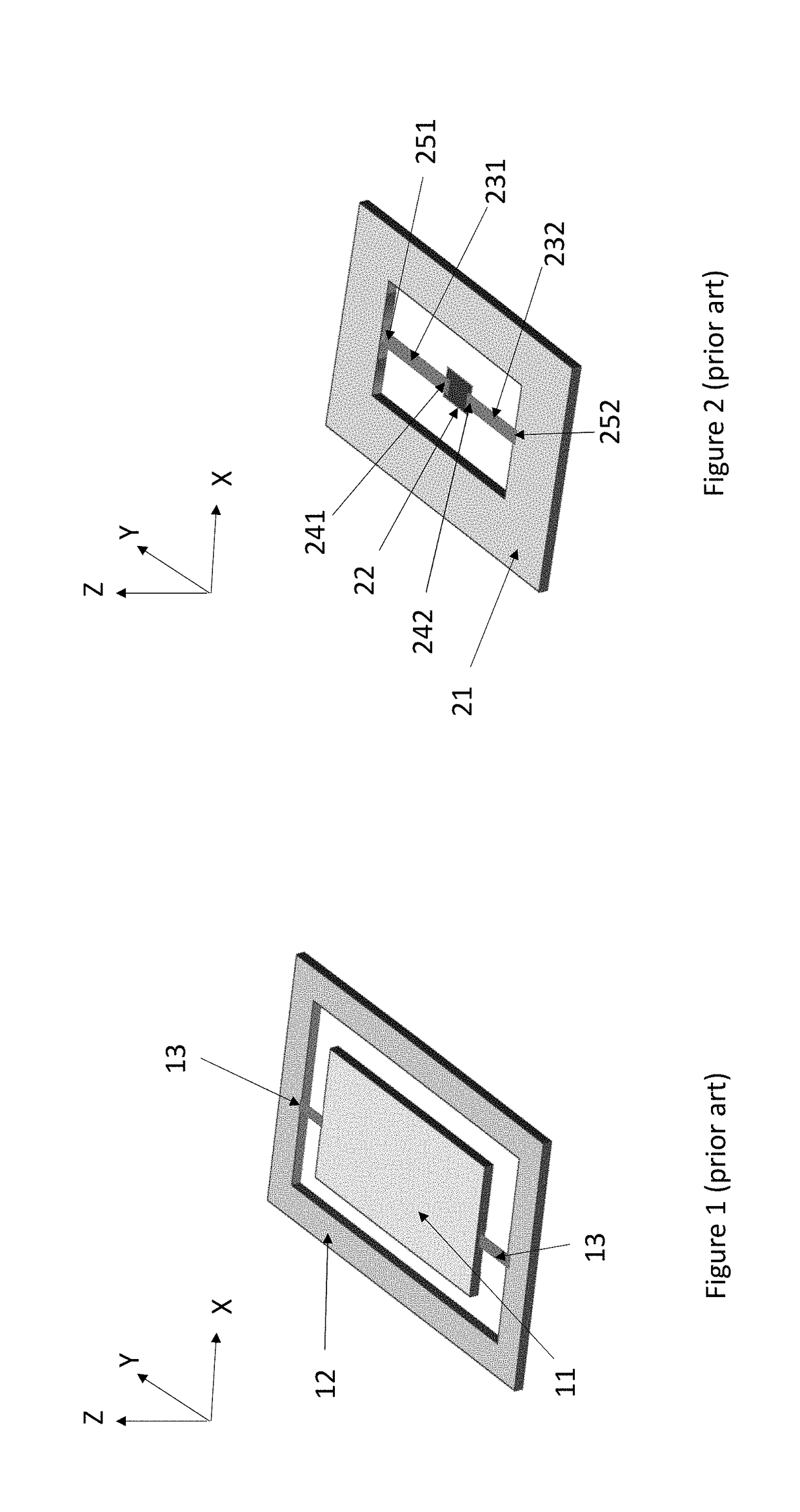
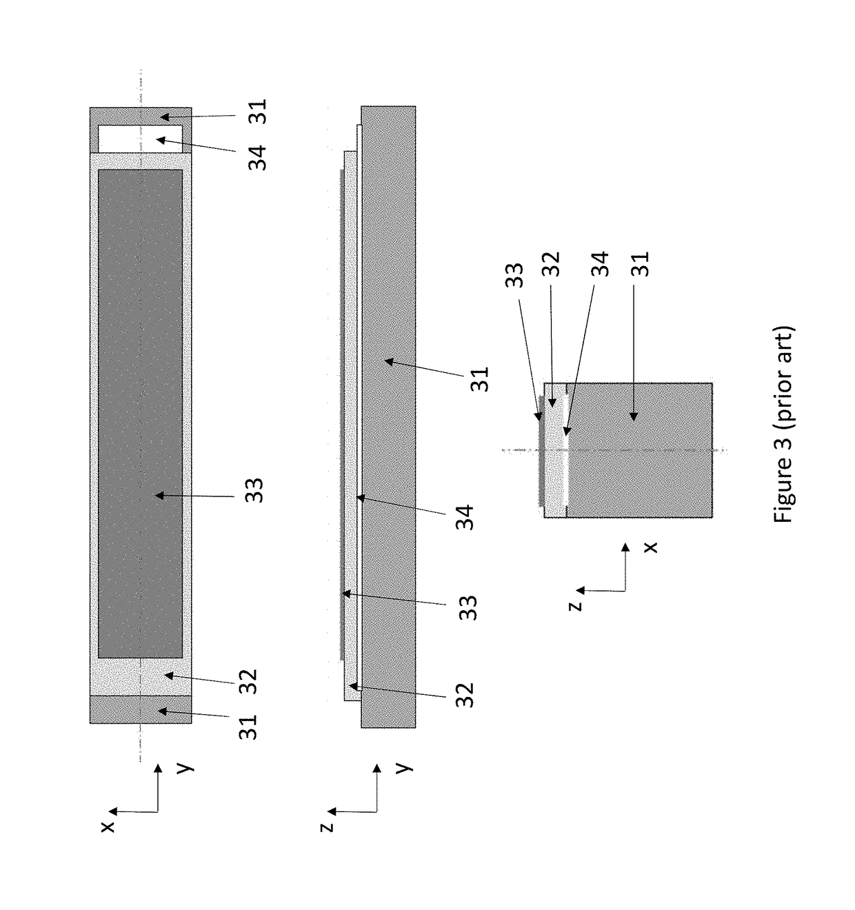
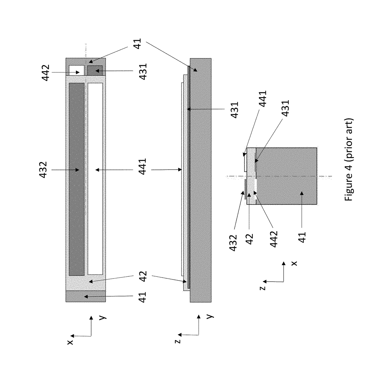
FIELD OF THE DISCLOSURE[0001]The present disclosure relates to MEMS resonators, and more particularly to MEMS resonators where one or more mass elements are driven into rotational motion by piezoelectric actuation or where the rotational motion of one or more mass elements is detected by piezoelectric means. The present disclosure further concerns gyroscopes and clock oscillators implemented with piezoelectric rotational MEMS resonators.BACKGROUND OF THE DISCLOSURE[0002]The resonators described in this disclosure comprise an inertial mass element suspended from at least one spring structure. The inertial mass element is set into primary oscillating motion by a periodic actuating force. It can be mechanically coupled to other mass elements.[0003]FIG. 1 shows a simplified illustration of a MEMS resonator structure. An inertial mass 11 is suspended from a fixed frame 12 by suspenders 13. In this disclosure a “fixed” object means an object which is much larger than the MEMS resonator st...

Claims


Application Information

Patent Timeline
Patent Type & Authority Applications(United States)
IPC IPC(8): H01L41/113H01L41/09G01C19/5642G01C19/5747G01C19/5712
CPCH01L41/1136H01L41/094G01C19/5642G01C19/5747G01C19/5712G01P15/125H03H9/02338H03H9/2405G01P2015/0862H10N30/306H10N30/2042
Inventor KUISMA, HEIKKI
Owner MURATA MFG CO LTD
Why Eureka
Try Eureka