Half mirror, light guide device, and display device

a technology of light guide device and half mirror, which is applied in the direction of optical light guide, optics, instruments, etc., can solve the problems of low light use efficiency and difficulty in producing half mirrors with desired optical properties, and achieve the effect of low reflectan

Inactive Publication Date: 2018-12-06
SEIKO EPSON CORP
View PDF17 Cites 2 Cited by
  • Summary
  • Abstract
  • Description
  • Claims
  • Application Information

AI Technical Summary

Benefits of technology

[0008]According to the first aspect of the invention, the anti-aggregation layer reduces aggregation of silver, and thus aggregation, which adversely affects the optical properties, is less likely to occur, enabling formation of a silver layer having a small thickness. Thus, a half mirror having desired optical properties and a low reflectance is obtained.
[0016]According to the second aspect of the invention, instead of the layer including only silver, the alloy layer including silver and the element X is employed. This reduces aggregation of silver, enabling formation of a silver alloy layer having a small thickness. Thus, a half mirror having desired optical properties and a low reflectance is obtained.

Problems solved by technology

Thus, if the incident angle of the light onto the half mirror is substantially the same as Brewster's angle due to the design of the display device, only the s-polarized component is used as image light, leading to low light use efficiency.
In such a case, it is difficult to produce a half mirror having desired optical properties.

Method used


Image

  • Half mirror, light guide device, and display device
  • Half mirror, light guide device, and display device
  • Half mirror, light guide device, and display device

Examples


first embodiment

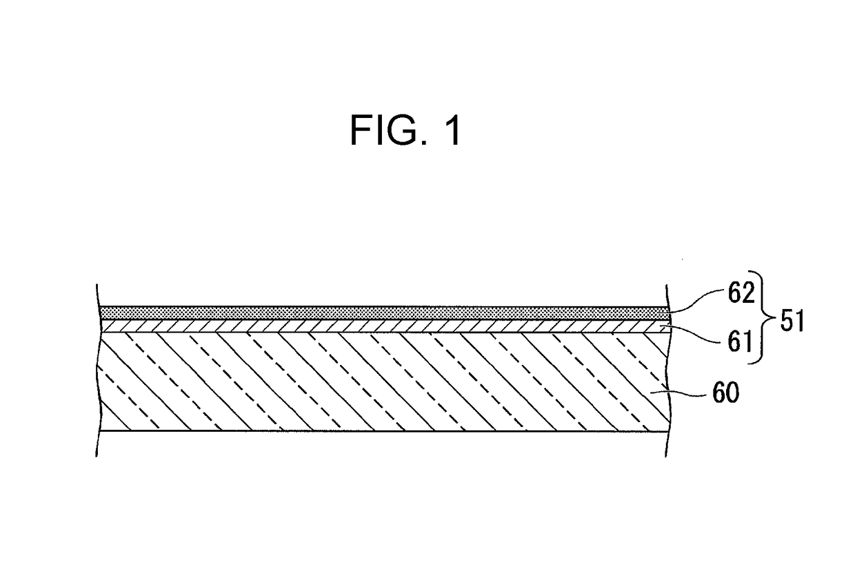
[0048]Hereinafter, a first embodiment of the invention is described with reference to FIG. 1 to FIG. 11. A half mirror according to this embodiment is preferably employed in a display device described below as a half mirror for extracting image light. FIG. 1 is a cross-sectional view of a half mirror according to the first embodiment. In the drawings, for ease of understanding of the components, the components are illustrated at different scales in some cases.

[0049]As illustrated in FIG. 1, a half mirror 51 according to the embodiment is disposed on a surface of a base 60. The half mirror 51 includes a silver layer 62 and an anti-aggregation layer 61 in contact with the silver layer 62. The silver layer 62 is disposed over the base 60. The anti-aggregation layer 61, which is a foundation layer of the silver layer 62, is disposed between the silver layer 62 and the base 60.

[0050]The base 60 is composed of a material having light transmissivity, such as glass and plastic. The thicknes...

second embodiment

[0079]Hereinafter, a second embodiment of the invention is described with reference to FIG. 12 to FIG. 20. A half mirror of the second embodiment has the same basic configuration as that of the first embodiment except for the configuration of the dielectric layers. FIG. 12 is a cross-sectional view of a half mirror of the second embodiment. In FIG. 12, components identical to those in the figures of the first embodiment are assigned the same reference numerals as those in the first embodiment and are not described.

[0080]As illustrated in FIG. 12, a half mirror 53 of this embodiment includes a first dielectric layer 81, a second dielectric layer 82, a third dielectric layer 83, a fourth dielectric layer 84, a fifth dielectric layer 85, a sixth dielectric layer 86, a silver layer 87, a seventh dielectric layer 88, an eighth dielectric layer 89, a ninth dielectric layer 90, a tenth dielectric layer 91, an eleventh dielectric layer 92, and an adhesive layer 93. The half mirror 53 of thi...

third embodiment

[0098]A display device of this embodiment is used as a head-mounted display configured to be worn on a user's head, for example. FIG. 18 is a cross-sectional view of a display device of this embodiment. FIG. 19 is a rear view of a light guide device seen from the side of the user. FIG. 20 is a view indicating optical paths of image light from the light guide device. In the following figures, for ease of understanding of the components, the components are illustrated at different scales in some cases.

Overall Configuration of Light Guide Device and Display Device

[0099]As illustrated in FIG. 18, a display device 100 includes an image forming device 10 and a light guide device 20. The light guide device 20 in FIG. 18 corresponds to the light guide device 20 taken along line XVIII-XVIII in FIG. 19. The display device 100 allows a user to see a virtual image provided by the image forming device 10 and to see through it. In the display device 100, a pair of the image forming device 10 and ...


PUM

PropertyMeasurementUnit
thicknessaaaaaaaaaa
reflectanceaaaaaaaaaa

Abstract

A half mirror includes a silver layer and an anti-aggregation layer in contact with the silver layer. The anti-aggregation layer may be composed of ITO or IGO. Alternatively, the anti-aggregation layer may be composed of an organic molecular film having a thiol group. Alternatively, the anti-aggregation layer may be composed of an alloy including silver in an amount of 97% or more and an element X, in which the element X is any one of Au, Mg, Zn, Cu, Al, Si, Pd, Sn, Pt, Ti, and Cr.

Description

BACKGROUND1. Technical Field[0001]The present invention relates to a half mirror, a light guide device, and a display device.2. Related Art[0002]As a wearable information appliance, an image display device worn on a user's head, such as a head-mounted display, has been recently provided. Furthermore, a see-through image display device is known. The see-through image display device allows the user wearing it to see an image composed of display elements and to see through it at the same time. The image display device of this type includes a half mirror that reflects image light toward the user's eyes and allows external light to pass therethrough toward the user's eyes.[0003]JP-A-2014-224891 discloses a half mirror including a silver layer, a first dielectric multilayer film including a first aluminum oxide layer and a titanium oxide layer, and a second dielectric multilayer including a zirconium oxide-based dielectric layer and a second aluminum oxide layer. JP-A-2014-224891 describe...

Claims


Application Information

Patent Timeline
Patent Type & Authority Applications(United States)
IPC IPC(8): G02B27/01G02B27/14F21V8/00
CPCG02B27/0172G02B27/142G02B6/0055G02B2027/0118G02B5/085G02B6/002G02B6/0035G02B6/0056
Inventor MATSUKI, HAYATOYANO, KUNIHIKOTAKEMURA, KOICHIYOSHIDA, SHOHEI
Owner SEIKO EPSON CORP
Why Eureka
Try Eureka