
Capacitive power transfer arrangement

a power transfer arrangement and capacitor technology, applied in the direction of lighting and heating apparatus, process and machine control, instruments, etc., can solve the problems of reducing consumer acceptance of such wireless applications, reducing design costs and resulting product costs, and reducing so as to increase the surface area of the heatsink, maximise the capacitance of the coupled capacitor, and easy to identify

Inactive Publication Date: 2018-12-06
SIGNIFY HLDG BV
View PDF0 Cites 1 Cited by
  • Summary
  • Abstract
  • Description
  • Claims
  • Application Information

AI Technical Summary

Benefits of technology

The patent is about a way to power wireless devices with low-cost power sources. This can make it easier and cheaper to create and operate devices that run on battery power.

Problems solved by technology

Many wireless devices such as sensors and controllers only require low power levels to operate.
However, the need to replace depleted batteries or to connect a rechargeable battery to a power supply can reduce consumer acceptance of such wireless applications.
However, most known kinds of wireless power transfer solutions generally require a dedicated IC and circuitry.
The design costs and resulting product costs may be unfavourably high, and the size of the power-donating device may also become unfavourably large as a result of having to include the additional components.
Therefore, consumer acceptance of such solutions may be quite low.

Method used


Image

  • Capacitive power transfer arrangement
  • Capacitive power transfer arrangement
  • Capacitive power transfer arrangement

Examples


Embodiment Construction

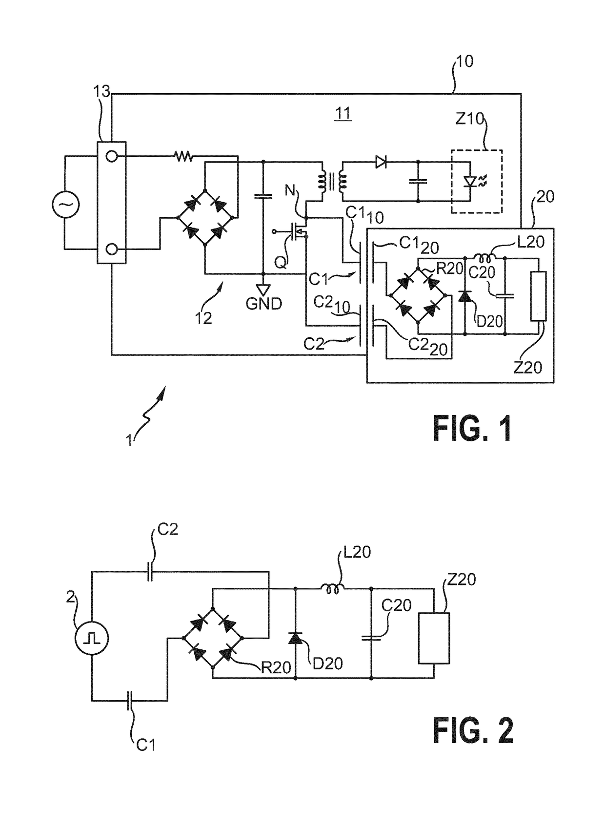
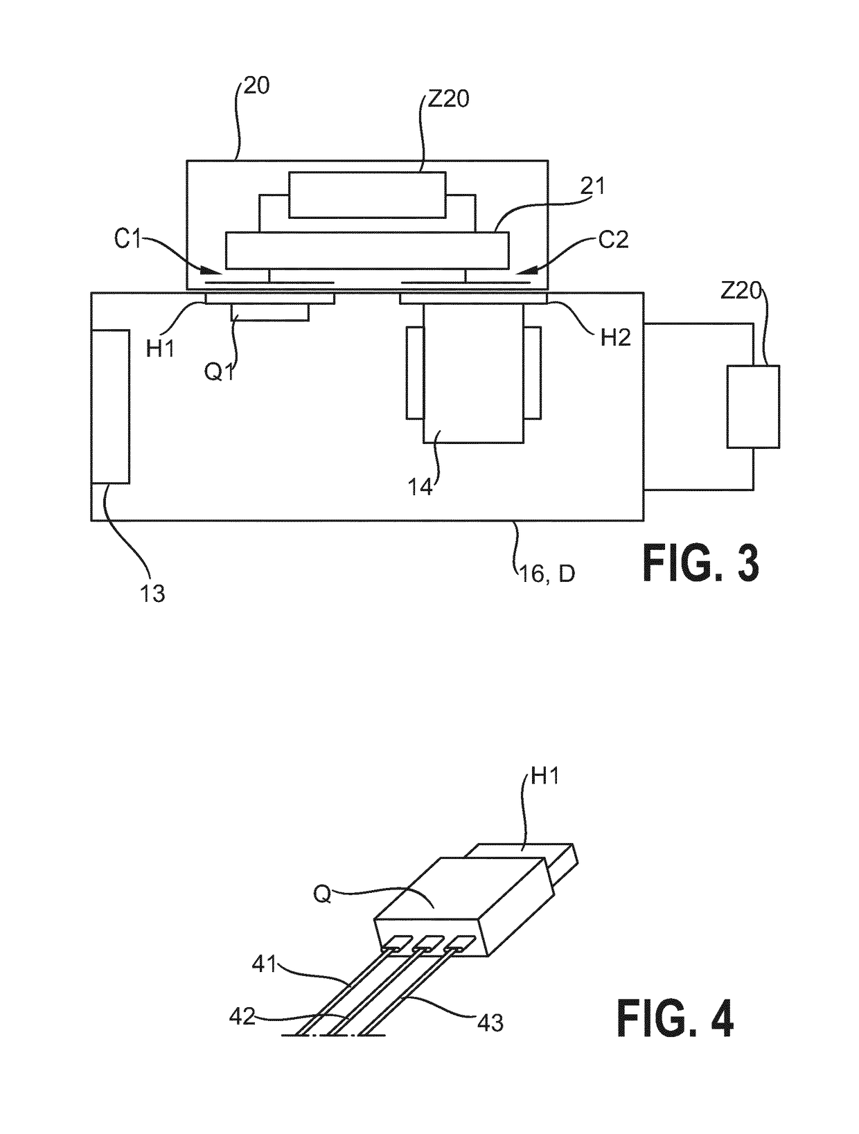
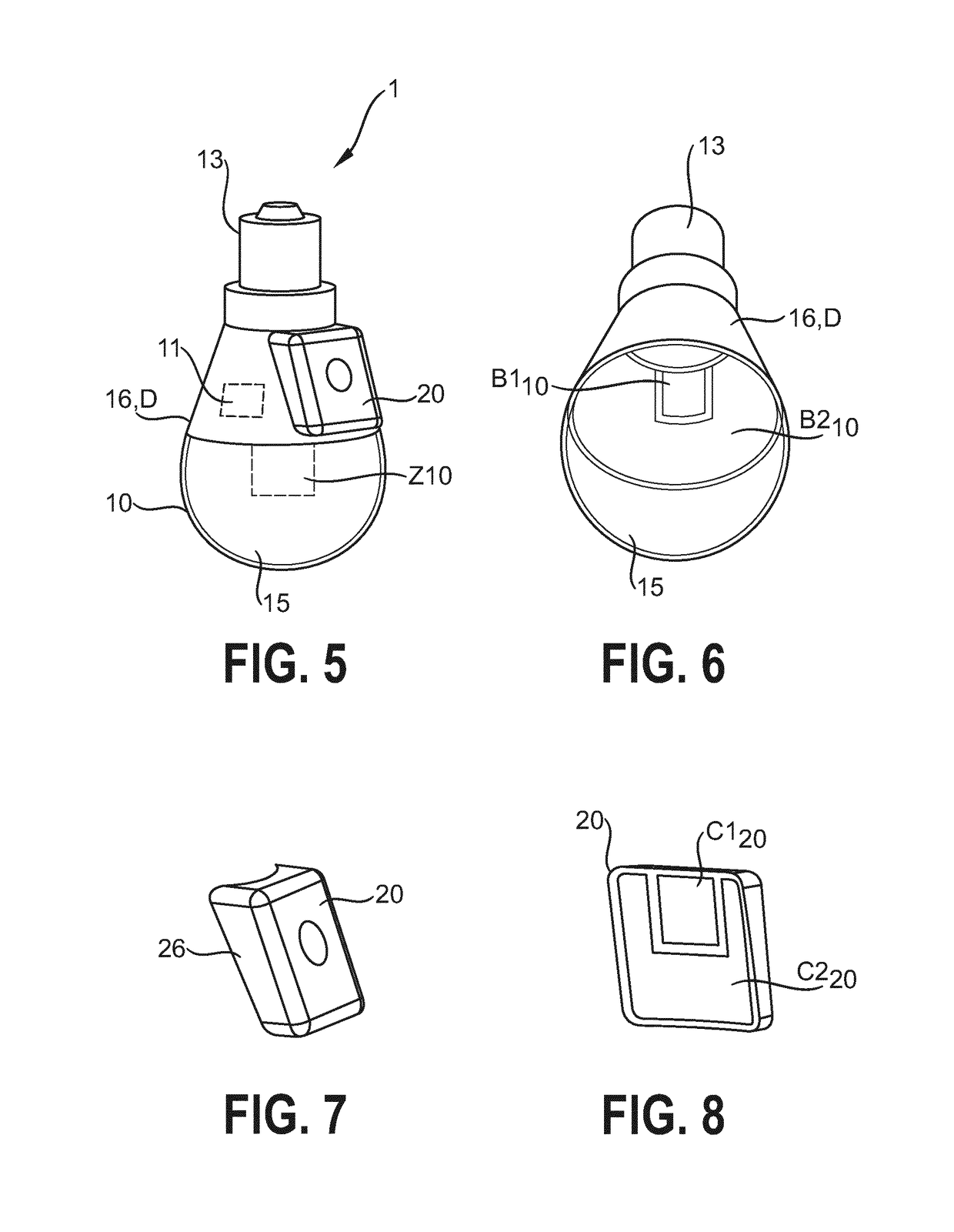
[0045]FIG. 1 shows a schematic circuit diagram of an embodiment of a capacitive power transfer arrangement 1 according to the invention, in a bipolar realisation with two coupled capacitors C1, C2 for transferring power from a first electrical device 10 to a second electrical device 20.

[0046]The first electrical device 10 is shown to have a driver 11 for driving a load Z10, in this case an LED light source L10. The driver 11 incorporates a diode bridge rectifier and a switched-mode power supply 12, in this case a flyback converter 12, to convert mains input to a DC output for the load Z10. The switched-mode power supply 12 uses a transistor switch Q, in this case a MOSFET 10, to perform rapid on / off switching of the DC output voltage in the usual manner when a pulse-width modulation control signal is applied to the control input of the transistor switch. In this exemplary embodiment, a first plate / electrode C110 of the first coupled capacitor C1 is electrically connected to node N a...


PUM


Abstract

The invention describes a capacitive power transfer arrangement (1) for transferring power between a first electrical device (10) and a physically independent second electrical device (20), which power transfer arrangement (1) comprises a number of coupled capacitors (C1, C2), and wherein a coupled capacitor (C1, C2) comprises a first electrode (C110, C210), which first electrode (C110, C210) comprises a heatsink (H1, H2) thermally coupled to a heat dissipating component (Q, 14) of a power supply (12) of the first electrical device (10); a second electrode (C120, C220) realized in the second electrical device (20); and a dielectric layer (D) formed by a housing (16, 26) of at least one of the electrical devices (10, 20). The invention further describes a method of performing capacitive power transfer from a first electrical device (10) to a physically independent second electrical device (20); a driver (11) of an electrical device (10); and n electrical device (10) comprising such a driver (11).

Description

FIELD OF THE INVENTION[0001]The invention describes a capacitive power transfer arrangement for transferring power between a first electrical device and a physically independent second electrical device. The invention also describes a method of performing capacitive power transfer; an electrical device driver; and an electrical device.BACKGROUND OF THE INVENTION[0002]There is a wide range of consumer devices available today that operate using wireless technology. Many wireless devices such as sensors and controllers only require low power levels to operate. Such applications could find use in many environments such as household, commercial and industrial. The power supply of a wireless device can be a battery. When the wireless device uses a re-chargeable battery as power supply, the device must be connected to a power source in order to re-charge. However, the need to replace depleted batteries or to connect a rechargeable battery to a power supply can reduce consumer acceptance of...

Claims


Application Information

Patent Timeline
Patent Type & Authority Applications(United States)
IPC IPC(8): H02J50/05H02J7/02F21K9/232F21K9/238F21V23/00F21V29/70H05B33/08H02M3/335H05K7/20F21V29/508H05B44/00
CPCH02J50/05H02J7/025F21K9/232F21K9/238F21V23/007F21V29/70H05B33/0815H02M3/33507H05K7/209F21V29/508F21Y2115/10H05B45/3725H05B45/382H05B45/385H05B45/357
Inventor SHI, LIANGWANG, GANGHE, FENG
Owner SIGNIFY HLDG BV
Learn More