Supercharge Your Innovation With Domain-Expert AI Agents!

Control area network (CAN) transceivers with automatic polarity detection

a control area network and transceiver technology, applied in the field of automotive systems, can solve the problems of module not being able to perform its function, module cannot perform its function, and actually cannot be detected

Active Publication Date: 2018-12-06
TEXAS INSTR INC
View PDF1 Cites 4 Cited by
  • Summary
  • Abstract
  • Description
  • Claims
  • Application Information

AI Technical Summary

Benefits of technology

The patent describes a way to use two CAN bus transceivers in a single circuit package, with the connections between them reversed to prevent interference. During standby mode, both transceivers are powered up and monitoring for wake up signals on the CAN bus. The correctly connected transceiver detects the signals and comes into full operating state, while the other transceiver stays in standby mode. This design allows for low power consumption and can protect the CAN bus from reverse connections without needing additional components or power.

Problems solved by technology

Modern automobiles are extremely complex.
However, in some cases the CAN bus wires from a given module are unintentionally reversed.
When this occurs, that module cannot communicate with the remaining modules, the module cannot then cannot perform its function and actually cannot be detected from tools connected to the CAN bus.
Therefore, diagnosis of the problem is difficult and functionality is lost.
Some attempts have been made to address the problem but they are more complicated, require more components and require more power.
As the standby mode consumes very low power, only nominal additional power is required.

Method used


Image

  • Control area network (CAN) transceivers with automatic polarity detection
  • Control area network (CAN) transceivers with automatic polarity detection
  • Control area network (CAN) transceivers with automatic polarity detection

Examples


Embodiment Construction

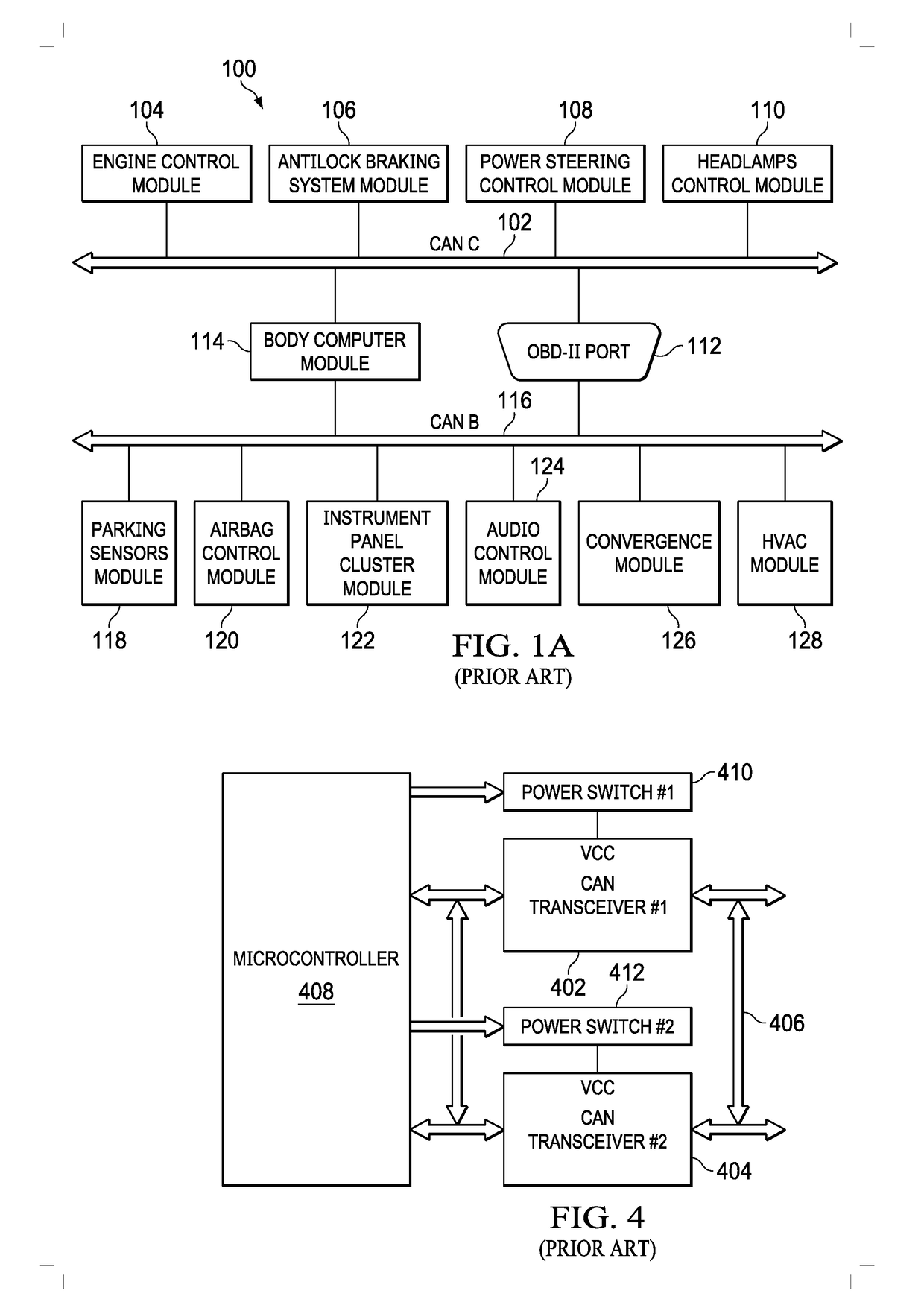
[0020]Referring now to FIG. 1A, a block diagram of the control system 100 of an automobile is illustrated. A CAN bus 102 in mode C has connected to it an engine control module 104, an antilock braking system module 106, a power steering control module 108, a headlamps control module no, an OBD-II port 112 and a body computer module 114. A CAN bus 116 in mode B is connected to the OBD-II port 112 and the body computer module 114 and has connected to it a parking sensors module 118, an airbag control module 120, an instrument contact panel cluster module 122, an audio control module 124, a convergence module 126 and an HVAC module 128. It is understood that these are just exemplary modules and additional modules or fewer modules could be present in a particular car, as could more or less CAN buses or alternative or additional buses.

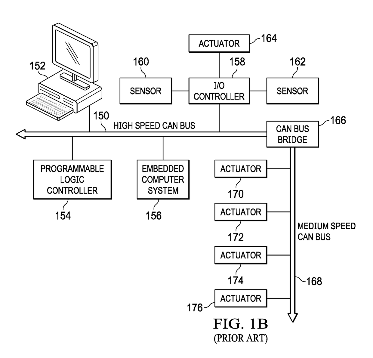
[0021]FIG. 1B is a block diagram of an industrial automation system according to the prior art. While automobiles may be the best known and most widespread...


PUM


Abstract

Two CAN bus transceivers utilized in a single integrated circuit package with the CAN bus connections between the two transceivers being inverted. Thus, one transceiver is connected to the CAN bus high and low lines while the other transceiver is connected to the CAN bus low and high lines. Both transceivers power up in a standby condition and each transceiver is monitoring for wake up signals on the CAN bus. The transceiver that is correctly connected to the CAN bus detects wake up signals. When the wake up signals are detected at that transceiver, that transceiver is brought to full operating state and the other transceiver is placed in a full standby condition. Additional input resistance is provided with each transceiver to maintain the proper input resistance for the integrated circuit.

Description

CROSS REFERENCE TO RELATED APPLICATIONS[0001]This application claims the benefit under 35 U.S.C. § 119(e) of U.S. Provisional Patent Application Ser. No. 62 / 513,302 entitled “Control Area Network (CAN) Transceivers with Automatic Polarity Detection and Correction” filed May 31, 2017, which is hereby incorporated by reference as if reproduced in its entirety.BACKGROUND1. Field[0002]The present design relates to automotive systems, and more particularly to controller area network (CAN) bus environments.2. Description of the Related Art[0003]Modern automobiles are extremely complex. There are numerous controller modules inside a given car to control the myriad of functions that exist in the car. For example, there are engine controller modules, transmission controller modules, door controller modules, light controller modules, body controller modules and so on. To avoid immense wiring issues, a CAN bus is used to interconnect the various controller modules. The CAN bus is a two wire bu...

Claims


Application Information

Patent Timeline
Patent Type & Authority Applications(United States)
IPC IPC(8): H04L12/40H04L12/12
CPCH04L2012/40215H04L2012/40273H04L12/40039H04L12/40032H04L12/12Y02D30/50H04L12/40013H04L12/40176
Inventor AAREY PREMANATH, ABHIJEETHHUBBARD, RICHARD EDWINROBERTSON, MAXWELL GUYGUPTA, LOKESH KUMARWENTROBLE, MARK EDWARDSPERLICH, ROLANDRADIC, DEJAN
Owner TEXAS INSTR INC
Features
  • R&D
  • Intellectual Property
  • Life Sciences
  • Materials
  • Tech Scout
  • Unparalleled Data Quality
  • Higher Quality Content
  • 60% Fewer Hallucinations
Learn More