Method of cleaning a high temperature food processing line in place and food sterilization line

a technology of high-temperature food processing and cleaning method, which is applied in the field of food processing, can solve the problems of unnecessary cleaning of processing equipment, product contamination, and unnecessary processing equipmen

Active Publication Date: 2018-12-13
SPX FLOW TECH DANMARK
View PDF7 Cites 5 Cited by
  • Summary
  • Abstract
  • Description
  • Claims
  • Application Information

AI Technical Summary

Problems solved by technology

A recurring problem when cleaning in place is that the same food product contaminates different processing equipment differently in a processing line comprising a given sequence of process elements through which the food product is transported.
This is highly disadvantageous as processing equipment having shorter cleaning times will be ready for use, yet standing idle, while the processing equipment having the longest cleaning time is being finally cleaned.
In particular, where some processing equipment is only minimally contaminated at the time when the most contaminated processing equipment is in need of cleaning; unnecessary processing equipment downtime, and if the processing line is so constructed also unnecessary processing equipment cleaning, constitutes a problem.

Method used


Image

  • Method of cleaning a high temperature food processing line in place and food sterilization line
  • Method of cleaning a high temperature food processing line in place and food sterilization line
  • Method of cleaning a high temperature food processing line in place and food sterilization line

Examples


example 1

[0134]The purpose of the test was to prove the feasibility of preparing aseptic samples while changing from one direct steam final heater or DSI-injector (Direct Steam Injection) to another during continuous sterile production.

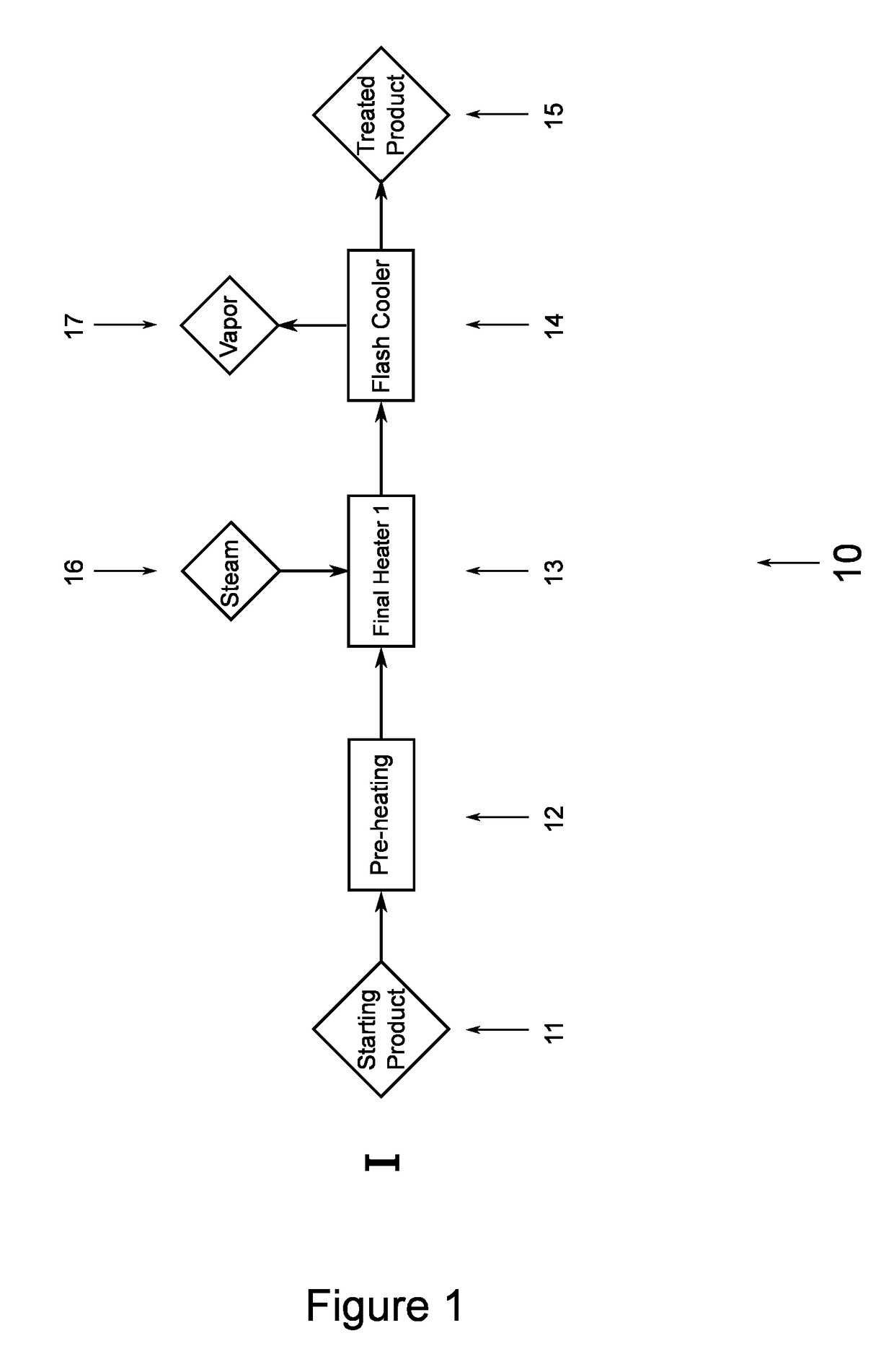
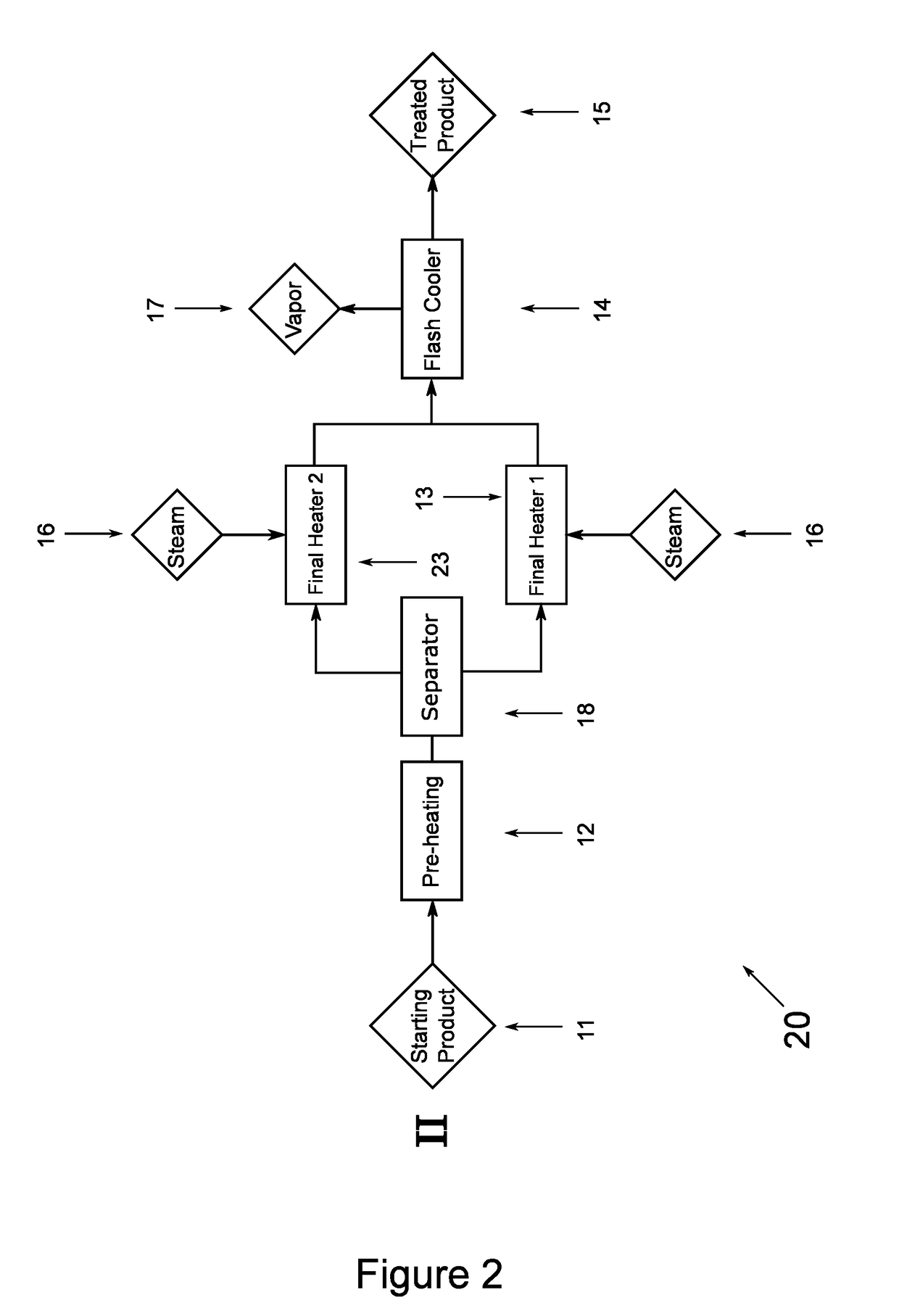
[0135]A full sterilization line (as in FIG. 5), with one common pre-heater and with two final direct steam heaters in parallel, the lines feeding into one common flash cooling vessel and further to a sterile cooling heat exchanger and a sterile packing machine. Milk samples for sterility testing were taken from samples packaged by the packaging machine.

[0136]12 kg skimmed milk powder (Arla Foods) was dissolved in 100 kg tap water (55° C.) (Flex-Mix Liquiverter) and hydrated for 30 minutes. Control samples were removed prior to passage of the processing line.

[0137]The plant was a 100 l / h SPP pilot UHT plant, with plates for preheating and cooling and mounted with double final heater steam injectors (first and second injectors) (Model: 17 mm / 2.66 mm). After prep...

example 2

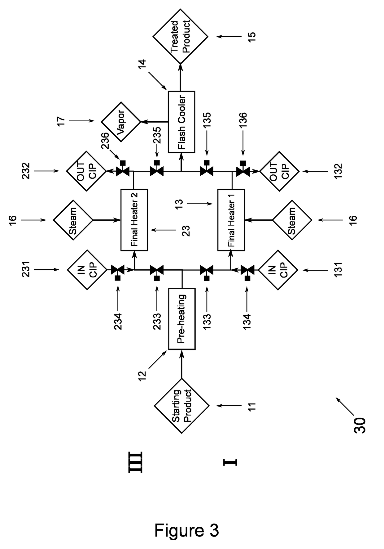
[0141]The test plant of Example 1 was used for testing the inline cleaning procedure after running the experiments of Example 1.

[0142]Lye (27.5% NaOH) was mixed with process water at 70° C. to a solution of 2.5% lye. The CIP-solution was poured into balance tank for a supply of cleaning agents in the CIP-procedure.

[0143]In a first test, the CIP-solution was pumped through the first DSI-injector of Example 1 at 55° C. and 150 L / h, and the conductivity of the CIP-solution was measured at the point of CIP-solution exit from the sequence of the production line comprising the first DSI-injector.

[0144]The time for the CIP-solution at exit to revert to the conductivity of the pure 2.5% lye solution was 90 s, corresponding to 3.75 l of CIP-solution having been pumped through the sequence of the production line comprising the first DSI-injector before returning to the initial conductivity.

[0145]In a second test, the CIP-solution was pumped through the entire production line via the second DS...


PUM

PropertyMeasurementUnit
temperatureaaaaaaaaaa
holding timeaaaaaaaaaa

Abstract

A high temperature food treatment method is disclosed wherein by alternatingly operating between a first final heater (13) and second final heater (23) arranged in parallel on a food processing line (30, 40, 50), it is possible to operate a continuous process, yet significantly reducing the overall downtime of the processing line (30, 40, 50), by performing a cleaning in place process on the final heater (13, 23), not currently being used in the high temperature food treatment process, thereby eliminating or significantly reducing the influence on the processing line (30, 40, 50) downtime by the process elements and / or processing equipment most easily contaminated.

Description

FIELD[0001]The present invention relates to the field of processing food and in particular to a method of cleaning a high temperature food processing line in place. Further the invention describes a high temperature food processing line configured to permit execution of the inventive method.BACKGROUND[0002]In the field of food processing, food product sterilization by heat treatment is a recurrent subject. The aim of food product sterilization by heat treatment is the reduction the number of microbiological entities or micro-organisms, such as e.g. bacteria, spores, yeast, mold, or bacteriophages. In particular, the removal of pathogens from the food product being heat treated is of particular importance.[0003]Modern food product processing plants are designed to reduce contamination within the processing lines through which the food product to be processed is transported. Important elements in this design is the use of low fouling and / or easy to clean and maintain materials such as...

Claims


Application Information

Patent Timeline
Patent Type & Authority Applications(United States)
IPC IPC(8): A23C7/02A61L2/07A61L2/18B08B9/032A23C3/033A23L2/46
CPCA23C7/02A61L2/07A61L2/18B08B9/0325A23C3/033A23L2/46A61L2202/17B08B9/0321
Inventor THORSEN, CLAUS
Owner SPX FLOW TECH DANMARK
Why Eureka
Try Eureka