
Propulsion system for an aircraft

a propulsion system and hybrid technology, applied in the direction of efficient propulsion technologies, machines/engines, transportation and packaging, etc., can solve the problems of engine starting in an unassisted manner, engine shutdown, and inability to provide starter system pneumatic power,

Active Publication Date: 2018-12-13
GENERAL ELECTRIC CO
View PDF4 Cites 36 Cited by
  • Summary
  • Abstract
  • Description
  • Claims
  • Application Information

AI Technical Summary

Benefits of technology

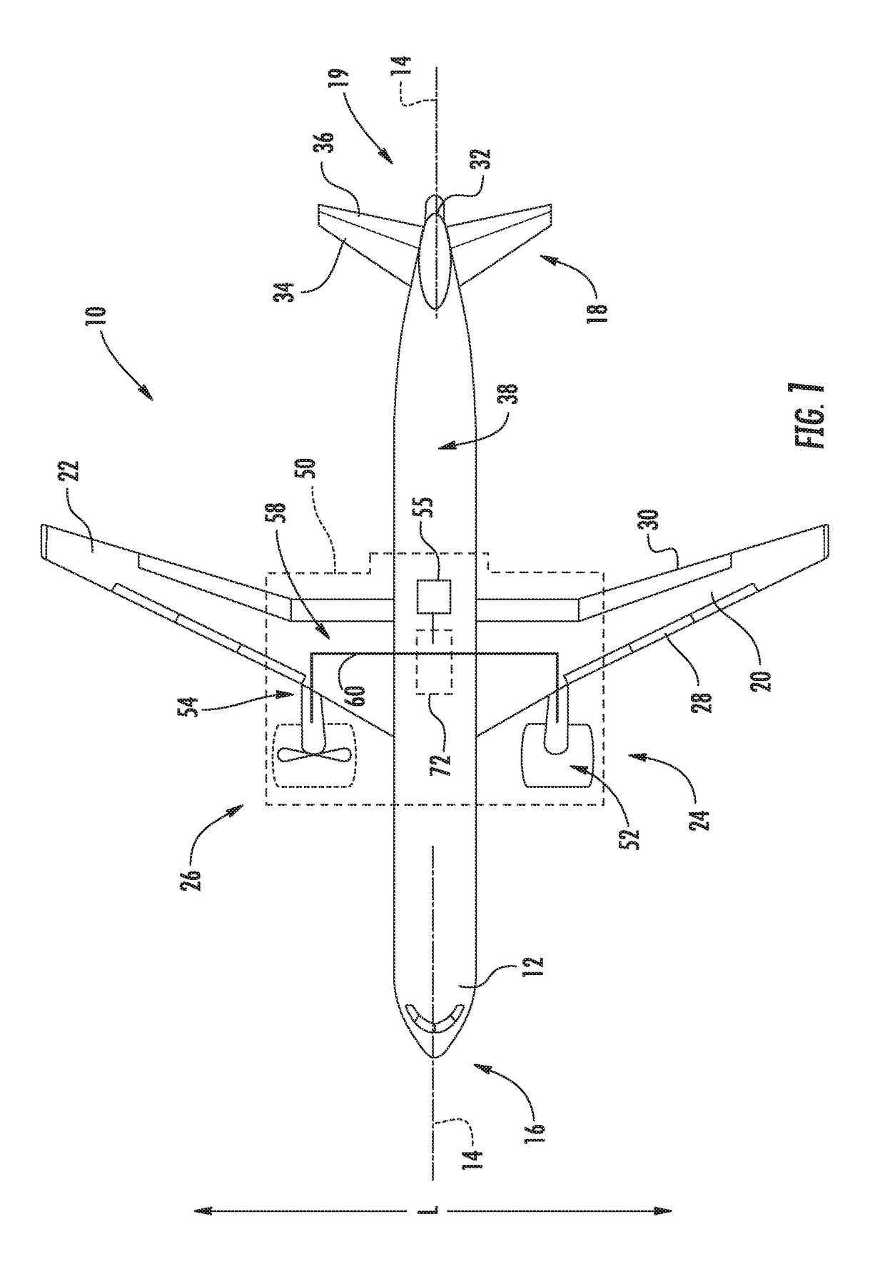
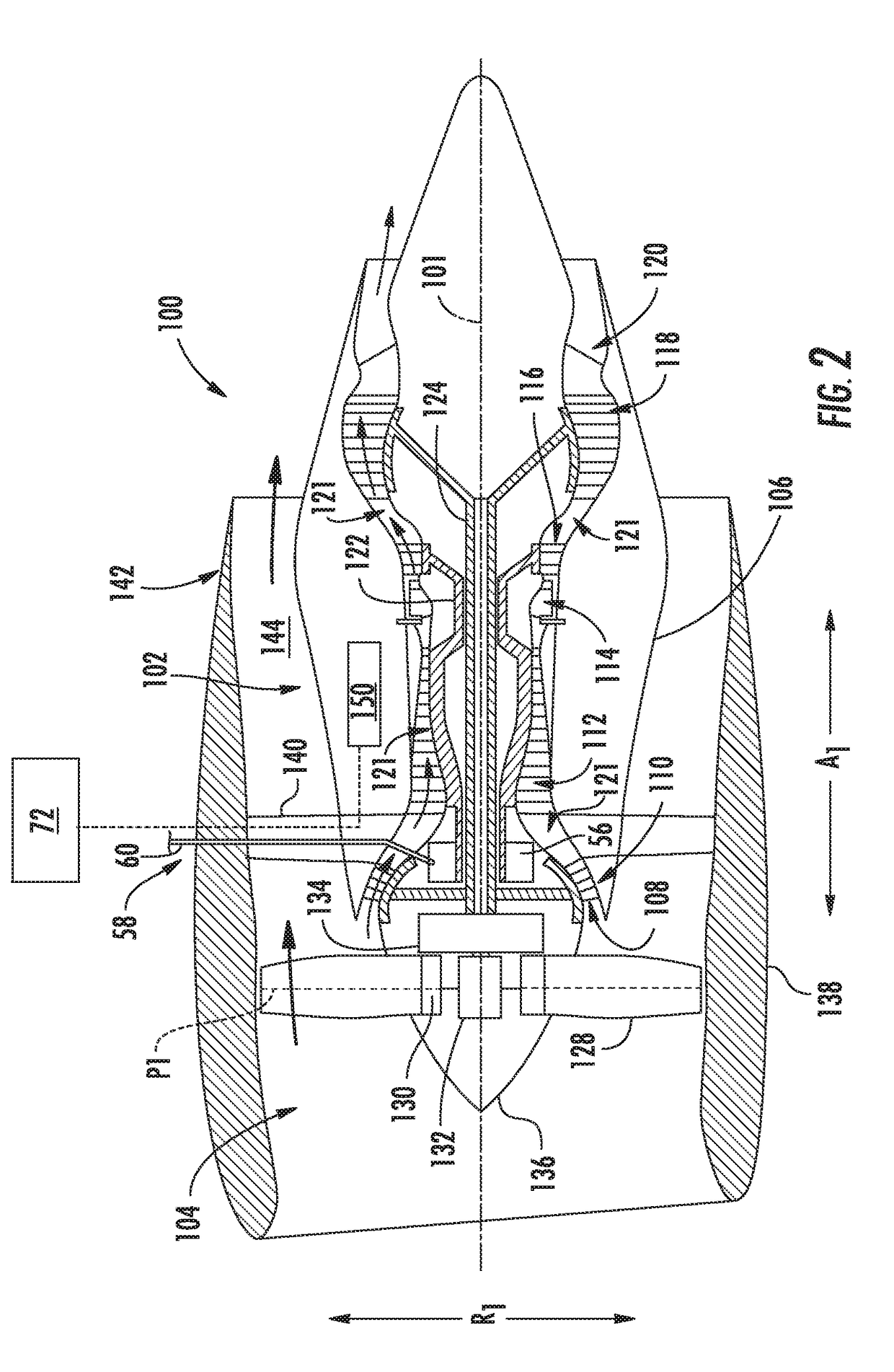
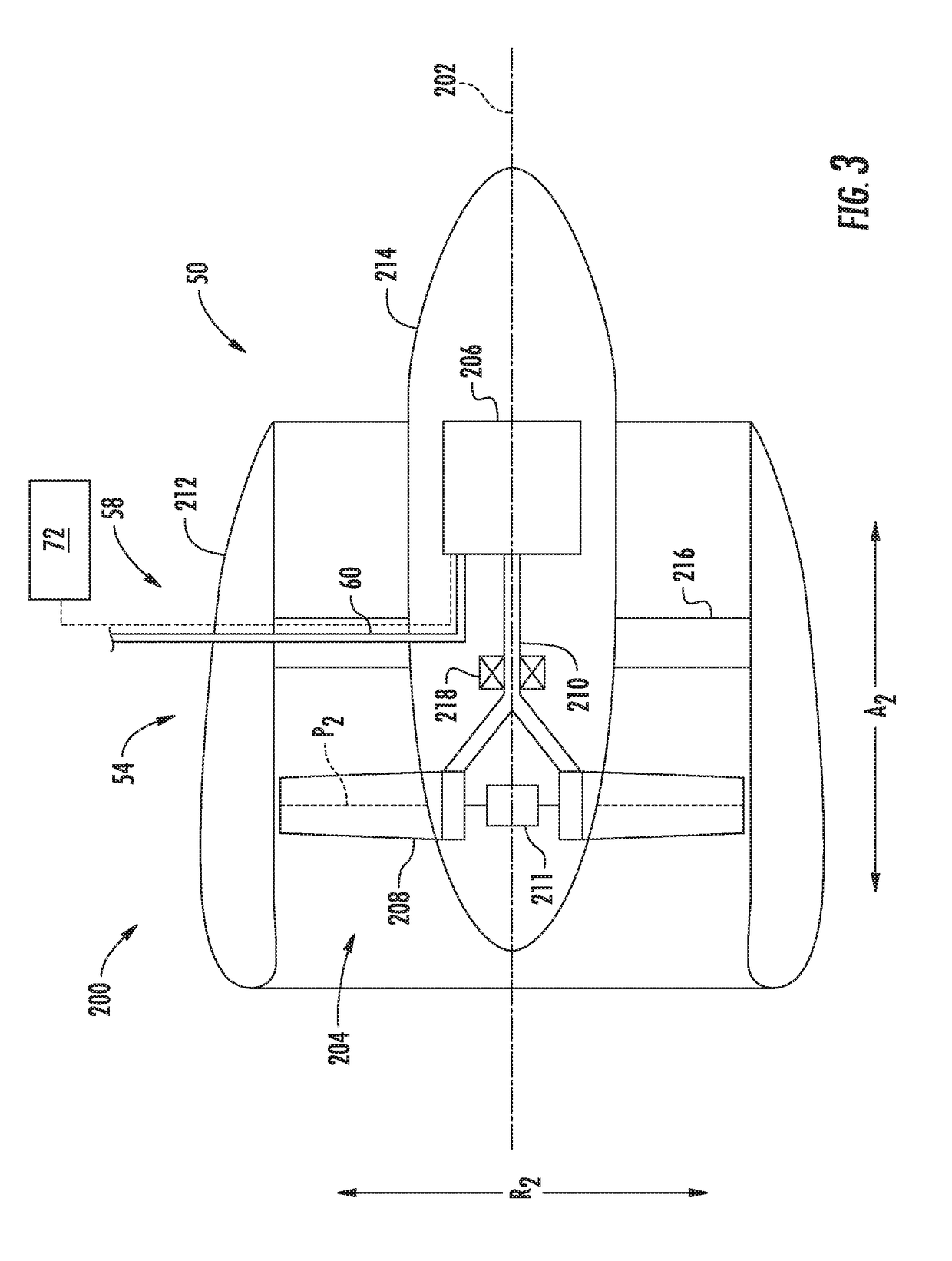
The present patent is about a method for starting a turbomachine in a hybrid-electric propulsion system of an aircraft. The system includes a propulsor, turbomachine, and an electrical system with two electric machines and an energy storage unit. The method involves receiving a command to start the engine, providing power to the first electric machine to rotate the turbomachine, igniting the combustor in the turbomachine, and providing power to the second electric machine to drive the propulsor. The technical effect is to provide a reliable and efficient starting system for the turbomachine in a hybrid-electric propulsion system of an aircraft.

Problems solved by technology

For example, the turbofan jet engine may shut down due to ice ingestions, bird strikes, inadvertent engine shutdown commanded by the flight crew, etc.
Regardless, engines are required to start in an unassisted manner under certain conditions due to the unavailability of power to the starter system.
If neither is running or running efficiently, pneumatic power might not be available to the starter system and hence a restart must be of the unassisted type.
Additionally, the lack of starter system torque in the unassisted case leads to higher internal temperatures, slower acceleration rates, and reduced compressor stall margin at any given acceleration rate when compared to an assisted start.
The factors may reduce a likelihood of a successful start, increase a time required to perform the restart, and potentially decrease a lifespan of certain components within the engine due to elevated internal temperatures.
Similarly, during assisted starts, traditional starter systems often provide sub-optimal torque contribution due to the limited torque / power capacity of the starter system and lack of ability to operate the starter at speeds approaching or surpassing engine idle speed.

Method used


Image

  • Propulsion system for an aircraft
  • Propulsion system for an aircraft
  • Propulsion system for an aircraft

Examples


Embodiment Construction

[0040]Reference will now be made in detail to present embodiments of the invention, one or more examples of which are illustrated in the accompanying drawings. The detailed description uses numerical and letter designations to refer to features in the drawings. Like or similar designations in the drawings and description have been used to refer to like or similar parts of the invention.

[0041]As used herein, the terms “first”, “second”, and “third” may be used interchangeably to distinguish one component from another and are not intended to signify location or importance of the individual components.

[0042]The terms “forward” and “aft” refer to relative positions within a gas turbine engine or vehicle, and refer to the normal operational attitude of the gas turbine engine or vehicle. For example, with regard to a gas turbine engine, forward refers to a position closer to an engine inlet and aft refers to a position closer to an engine nozzle or exhaust.

[0043]The terms “upstream” and “...


PUM


Abstract

A hybrid-electric propulsion system for an aircraft includes a propulsor and a turbomachine. The turbomachine includes a high pressure turbine drivingly coupled to a high pressure compressor through a high pressure spool. The hybrid electric propulsion system further includes an electrical system including a first electric machine, a second electric machine, and an electric energy storage unit electrically connectable to the first and second electric machines. The first electric machine is coupled to the high pressure spool of the turbomachine and the second electric machine is coupled to the propulsor for driving the propulsor to provide a propulsive benefit for the aircraft. The hybrid electric propulsion system also includes a controller configured to provide electrical power from an electric power source to the first electric machine to drive the first electric machine to start, or assist with starting, the turbomachine.

Description

FIELD[0001]The present subject matter relates generally to a hybrid-electric aircraft propulsion system, and a method for starting a turbomachine within the hybrid-electric aircraft propulsion system.BACKGROUND[0002]A conventional commercial aircraft generally includes a fuselage, a pair of wings, and a propulsion system that provides thrust. The propulsion system typically includes at least two aircraft engines, such as turbofan jet engines. Each turbofan jet engine is typically mounted to a respective one of the wings of the aircraft, such as in a suspended position beneath the wing, separated from the wing and fuselage.[0003]Initially, the turbofan jet engines must be started. Additionally, it may be necessary to start, or more particularly to re-start, one or more of the turbofan jet engines during a flight in the event of an unscheduled shutdown of the turbofan jet engine. For example, the turbofan jet engine may shut down due to ice ingestions, bird strikes, inadvertent engine...

Claims


Application Information

Patent Timeline
Patent Type & Authority Applications(United States)
IPC IPC(8): B64D27/24B64D27/10B64D35/08B64D31/06
CPCB64D27/24B64D27/10B64D35/08B64D2027/026B64D27/02B64D31/02B64D31/06B64D27/026F01D15/10F02K5/00F02C6/00F02C6/14F02C7/262F02C7/268F02C7/36F05D2220/76Y02T50/60
Inventor HON, ROBERT CHARLESGANSLER, MICHAEL THOMAS
Owner GENERAL ELECTRIC CO
Learn More