
Control system and method for pressure-let-downs stations

a control system and pressure-let-down technology, applied in the direction of container discharge methods, pipe heating/cooling, lighting and heating apparatus, etc., can solve the problems of high temperature drop, low efficiency, and inconvenient operation of depressurization systems using transcritical heat pumps

Active Publication Date: 2018-12-13
NUOVO PIGNONE SPA
View PDF4 Cites 18 Cited by
  • Summary
  • Abstract
  • Description
  • Claims
  • Application Information

AI Technical Summary

Benefits of technology

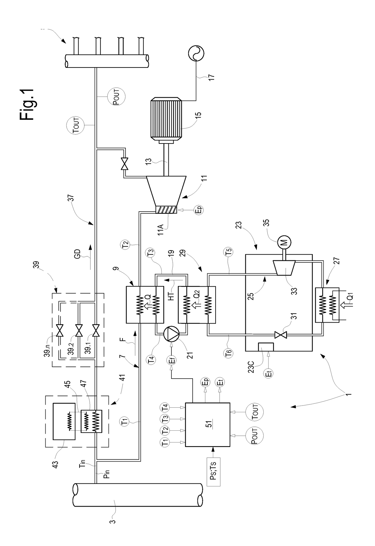
The patent is about a controller for a heat pump that adjusts the flow rate of the heat transfer fluid based on the temperature differences between the gas and the fluid at the inlet and outlet of the heat exchanger. This helps to achieve the optimal performance of the heat pump.

Problems solved by technology

However, the pressure drop being the same, an expansion process through a turboexpander, which generates mechanical power, causes a much higher temperature drop than a JT valve.
Considering the revenue stream generated by the power generated by the expander versus the extra-amount of expenditure for heating, the resulting margin is so slim that it rarely justifies the higher investments required by complex machinery, as the turboexpander and electric generator.
However, it turned out that depressurization systems using transcritical heat pumps may not be expedient under certain operating conditions, namely when the gas flow rate is reduced with respect to a design flow rate through the expander.
Similar limitations and drawbacks are also encountered if a standard, i.e. non-transcritical, heat pump is used as a heating means for heating the pressurized gas prior to expansion in the expander.

Method used


Image

  • Control system and method for pressure-let-downs stations
  • Control system and method for pressure-let-downs stations
  • Control system and method for pressure-let-downs stations

Examples


Embodiment Construction

[0028]The following detailed description of exemplary embodiments refers to the accompanying drawings. The same reference numbers in different drawings identify the same or similar elements. Additionally, the drawings are not necessarily drawn to scale. Also, the following detailed description does not limit the invention. Instead, the scope of the invention is defined by the appended claims.

[0029]Reference throughout the specification to “one embodiment” or “an embodiment” or “some embodiments” means that the particular feature, structure or characteristic described in connection with an embodiment is included in at least one embodiment of the subject matter disclosed. Thus, the appearance of the phrase “in one embodiment” or “in an embodiment” or “in some embodiments” in various places throughout the specification is not necessarily referring to the same embodiment(s). Further, the particular features, structures or characteristics may be combined in any suitable manner in one or ...


PUM


Abstract

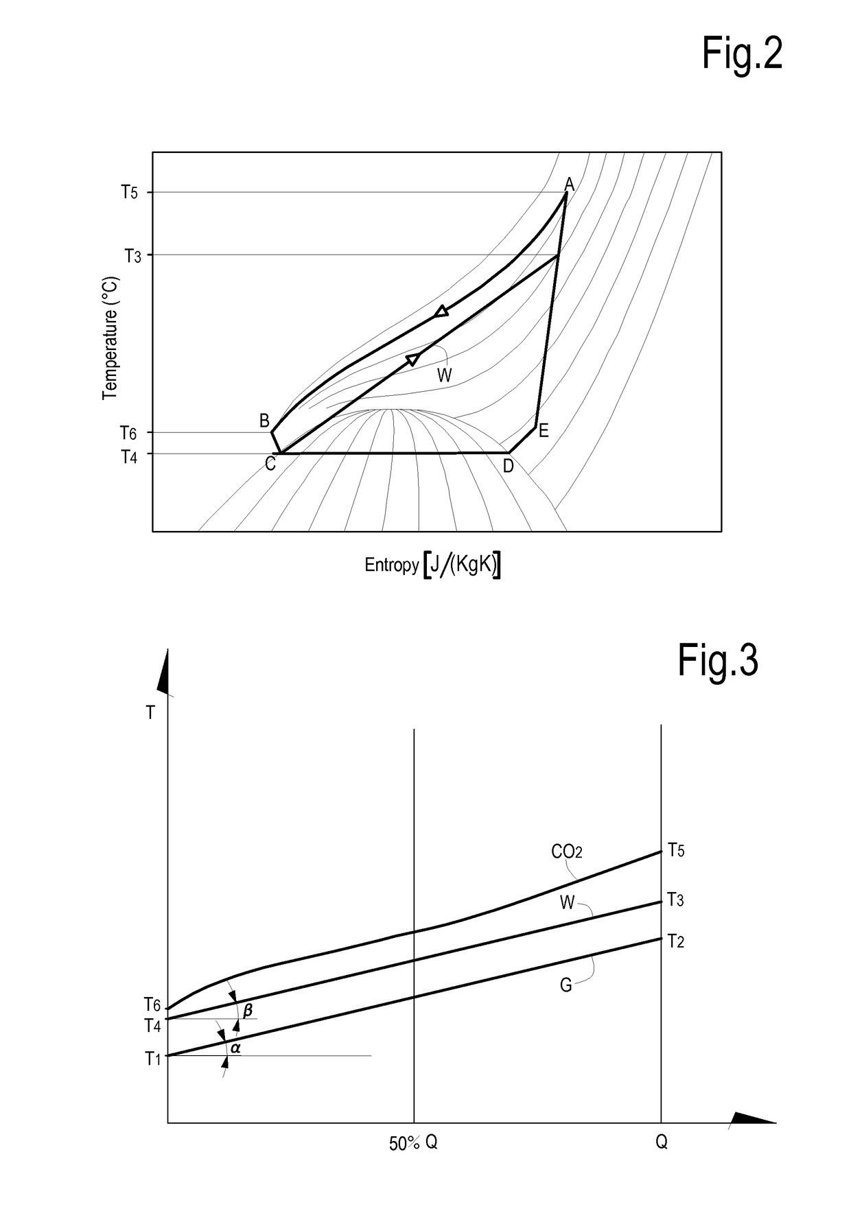
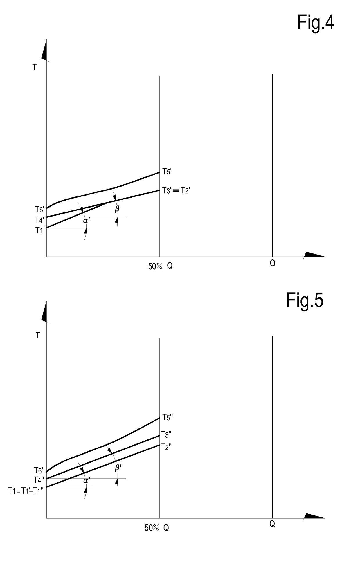
A system for depressurizing a gas in a pipeline is described. The system com-prises an expander configured and arranged for generating mechanical power by expanding gas from a first pressure to a second pressure. The system further comprises a heat pump and a heat transfer circuit containing a heat transfer fluid circu-lating therein, for receiving heat from the heat pump and delivering heat to the gas through a heat exchanger. A controller is further provided, configured and arranged for modulating a flow rate of the heat transfer fluid circulating in the heat transfer circuit as a function of a heat rate to be transferred from the heat transfer fluid to the gas, particularly as a function of temperature differentials between the gas and the heat transfer fluid at a gas inlet side and a gas outlet side of the heat exchang-er.

Description

TECHNICAL FIELD[0001]The disclosure relates to gas transportation. More specifically, the disclosure relates to so-called pressure-let-down stations, where a pressurized gas is de-pressurized for distribution in a distribution grid, at a lower pressure. Embodiments disclosed herein relate to systems and methods for providing efficient depressurization of the gas and at least partial recovery of the pressure energy.BACKGROUND[0002]Gas is one of the primary sources of energy used for both domestic as well as industrial uses. Natural gas, usually comprised of a mixture of hydrocarbons, is transported through transportation pipelines over long distances and then distributed in distribution networks or grids.[0003]Gas is transported in the transportation pipelines at relatively high pressure, for instance in the range of 55-65 bar. In a distribution network, where through gas is distributed to final users, gas is present at a substantially lower pressure, e.g. in the range of 6-24 bar, d...

Claims


Application Information

Patent Timeline
IPC IPC(8): F17D1/05F17D1/075
CPCF17D1/05F17D1/075F16L53/30F17C13/10F17C2223/035F17C2223/0123F17C2221/032F17C2225/033F17C2225/0123F17C2225/035F17C2227/0323F17C2227/039F17C2250/0626F17C2250/0631F17C2265/068F17C2221/033F17C2227/0309F17C2227/0316F17C2250/043F17C2250/0439F17C2250/0636F17C2265/07F25B11/02F25B49/00
Inventor MONTI, FRANCESCAAMIDEI, SIMONE
Owner NUOVO PIGNONE SPA
Learn More